


7
Where an existing chimney or vent is to be used, be sure that the
chimney or vent has adequate capacity for the number and sizes
of gas appliances being vented through it. Inspect the chimney
or vent and remove all soot or other obstructions, which will retard
free draft.
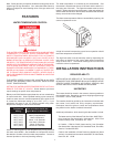
Vent piping making horizontal runs must have a minimum upward
slope toward the chimney or vent of 1/4” per foot. Vent pipe
length should be kept as short as possible. Be sure that the vent
pipe does not extend beyond the inside wall of a chimney.
In venting systems, where a continuous or intermittent back
(positive) draft is found to exist, the cause must be determined
and corrected. In some cases, a special vent cap may be required.
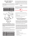
WATER LINE CONNECTIONS
The water heater may be installed by itself, or with a separate
storage tank, on both single and two-temperature systems. When
used with a separate storage tank, the circulation may be either
by gravity or by means of a circulating pump.
SYSTEM CONNECTIONS
The system installation must conform to these instructions and to
the local code authority having jurisdiction. Good practice requires
that all heavy piping be supported.
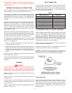
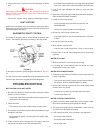
THERMOMETERS (Not supplied)
Thermometers should be obtained and field installed as shown
in the installation diagrams.
Thermometers are installed in the system as a means of detecting
the temperature of the outlet water.
RELIEF VALVE
This water heater has been provided with an ASME rated pressure
and temperature relief valve.
In addition to the appliance relief valve, each remote storage tank,
which may be used in conjunction with this appliance, shall also
be installed with a properly sized, rated and approved temperature
(ANSI) and pressure (ASME) relief valve(s).
WARNING
THE PURPOSE OF A RELIEF VALVE IS TO AVOID EXCESSIVE
PRESSURE OR TEMPERATURE INTO THE STEAM RANGE,
WHICH MAY CAUSE SCALDING AT FIXTURES, TANK
EXPLOSIONS, SYSTEM OR HEATER DAMAGE. NO VALVE IS
TO BE PLACED BETWEEN THE RELIEF VALVE AND THE
TANK.
A DRAIN LINE MUST BE CONNECTED TO THE RELIEF VALVE
TO DIRECT DISCHARGE TO A SAFE LOCATION TO AVOID
SCALDING OR WATER DAMAGE. THIS LINE MUST NOT BE
REDUCED FROM THE SIZE OF THE VALVE OUTLET AND
MUST NOT CONTAIN VALVES, RESTRICTIONS NOR SHOULD
IT BE LOCATED IN FREEZING AREAS. DO NOT THREAD OR
CAP THE END OF THIS LINE. RESTRICTED OR BLOCKED
DISCHARGE WILL DEFEAT THE PURPOSE OF THE VALVE
AND IS UNSAFE. DISCHARGE LINE SHALL BE INSTALLED
TO ALLOW COMPLETE DRAINAGE OF BOTH THE VALVE AND
LINE.
Your local code authority may have other specific relief valve
requirements.
GAS PIPING
Contact your local gas service company to ensure that adequate
gas service is available and to review applicable installation codes
for your area.
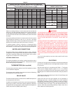
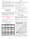
Size the main gas line in accordance with Table 3. The figures
shown are for straight lengths of pipe at 0.3 in. w.c. pressure
drop, which is considered normal for low-pressure systems. Note
that fittings such as elbows and tees will add to the pipe pressure
drop.
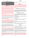
Equivalent lengths of standard pipe in feet for listed fittings (add
below values to Table 3).
Install vent lines from main gas regulator and (if applicable) a
diaphragm gas valve. Vent line should be run to the outside of
the building, terminating clear of windows or fresh air intakes.
Outside terminal of vent should have a screen to prevent insects
from building nests in vent pipe. The vent should terminate in a
manner, which will preclude the possibility of water, snow, dirt or
other matter from entering the line.
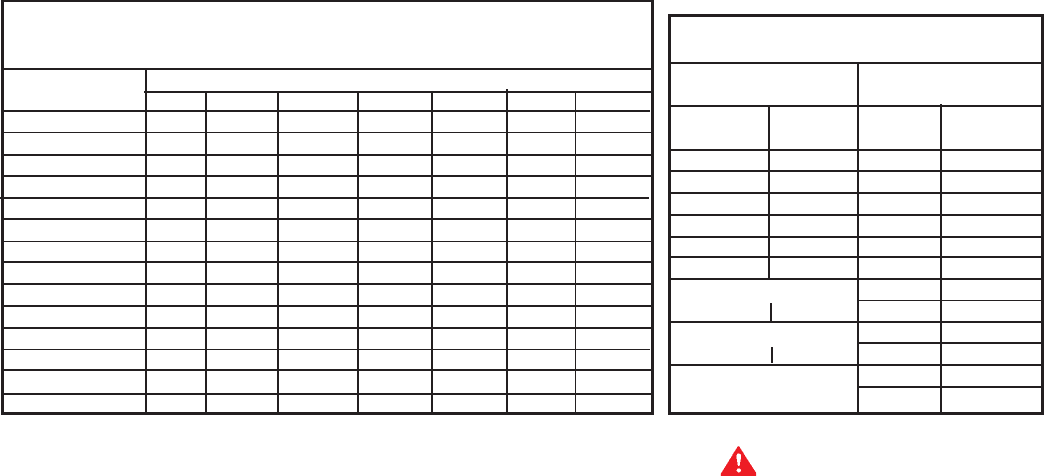
CORRECTION FACTORS
Specific Gravity Pressure Drop
Other than 0.60 Other than 0.3
Specific Multplier Pressure Multiplier
Gravity Drop
0.50 1.10 0.1 0.577
0.60 1.00 0.2 0.815
0.70 0.926 0.3 1.00
0.80 0.867 0.4 1.16
0.90 0.817 0.6 1.42
1.00 0.775 0.8 1.64
Propane - Air 1.0 1.83
1.10 0.740 2.0 2.58
Propane 3.0 3.16
1.55 0.622 4.0 3.65
6.0 4.47
8.0 5.15
CAPACITY OF PIPE - NATURAL GAS IN CUBIC FEET PER HOUR
Maximum Based Upon Pressure Drop of 0.3” w.c. and Specific Gravity
of 0.60 and Maximum Gas Pressure of .5 psig.
Pipe Length Pipe Size - Inches (IPS)
In Feet 1 1 1/4 1 1/2 2 2 1/2 3 4
10 520 1050 1600 3050 4800 8500 17500
20 350 730 1100 2100 3300 5900 12000
30 285 590 890 1650 2700 4700 9700
40 245 500 760 1450 2300 4100 8300
50 215 440 670 1270 2000 3600 7400
60 195 400 610 1150 1850 3250 6800
70 180 370 560 1050 1700 3000 6200
80 170 350 530 990 1600 2800 5800
90 160 320 490 930 1500 2600 5400
100 150 305 460 870 1400 2500 5100
125 130 275 410 780 1250 2200 4500
150 120 250 380 710 1130 2000 4100
175 110 225 350 650 1050 1850 3800
200 100 210 320 610 980 1700 3500
NOTE: Use Multiplier at right for other specific gravities and pressure drops.
TABLE 2