


10
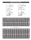
ELECTRICAL DATA
GENERAL
the characteristics of the branch circuit electrical supply. Do not
connect the water heater to an improper source of electricity.
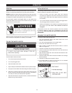
Do NOT energize the branch circuit for any reason before the water
elements to fail.
The installation must conform to these instructions and the local
connected to the water heater must also conform to the National
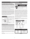
BRANCH CIRCUIT
The branch circuit wire size should be established through reference
sources in conjunction with the water heater amperage rating. Wire
is suggested the electrician size the branch circuit at 125 percent of
the water heater rating and further increase wire size as necessary
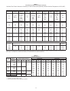
HEATER CIRCUITS
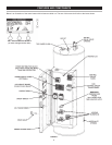
The model and rating plate provides heater circuit ratings. There are
Control Circuit: Power supply for the electromagnetic
this manual starting on page 12.
Power Circuit:
carries the heating element load.
The following section and pages describe the water heater circuits
and includes wiring diagrams.
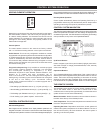
CONTROL CIRCUITS
The water heater is equipped with an electronic control system.
and element current sensors for monitoring the power circuits. Refer
Sequence of Operation
1. When the control is powered, the UIM should display model
information, water temperature, operating setpoint, heating
status and operating mode.
2. If the control determines that the actual water temperature inside
the tank is below the programmed operating setpoint minus the
programmed differential setpoints for each heating element.
4. The control remains in the heating mode until the water
this point the contactors will be de-energized.
5. The control system now enters the standby operating mode
while continuing to monitor the water temperature and the state
of other system devices. If the water temperature drops below
setpoint, the control will automatically return to step 2 and repeat
the heating cycle.
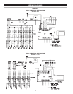
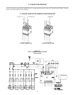
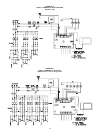
POWER CIRCUIT
The following wiring diagrams are included in this manual to show
typical arrangements of electrical components in the control and
power circuits by voltage and phase characteristics. They are to be
used as a reference by the installer or servicer in performing their
the heater.