50
F
A
B
C
E
2
0.5 x 45°
D 0/-0.1
∅G
1080
0100
1090
0010
1700
1410
TG MAG A B C D E F G
TG MAG 15-50
M 10 12 160 10,5 10 8 7,8
TG MAG 23-65
TG MAG 58-80
M 12 15 205 13,5 10 10 9,4
TG MAG 86-100
TG MAG 185-125 M 16 20 240 17 10 13 13
A.0500.551 – IM-TGMAG/02.00 EN (02/2008)
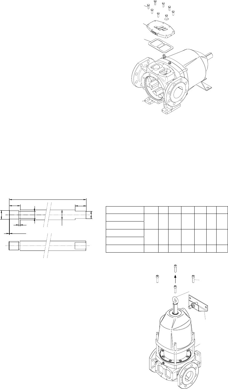
4.2.2 Disassembly of top cover (0100) or safety relief valve
1. Un-tighten tap bolts (1080) crosswise and remove them
2. Take off top cover (0100) or safety relief valve.
3. Remove gasket (1090) and clean the
sealing faces on the pump casing (0010)
and top cover (0100) or safety relief valve.
4.2.3 Disassembly of bearing bracket
Removal of bearing bracket
1. Place the pump in vertical position with the pump shaft pointing up on the work bench.
2. Remove bearing bracket support (1700).
3. Un-tighten cap head screws (1410) crosswise and remove them.
4. Mount the 4 guiding bars (tool) into the holes of cap head screws (1410) and screw lifting eye
bolt in the shaft end.
5. Lift the bearing bracket complete with
pump shaft and outer magnet rotor off the pump.
Remark: The guiding bars are necessary to prevent
that the magnets in the outer rotor are damaged
during disassembly of the bearing bracket.
Protect metal part with plastic tube.
Lifting eye bolt
Tool


