


8
installed in the square opening in the oor of the cold water basin of
one or more cells—sealed against leakage, and attached by machine
bolts, according to the installation drawing included. An appropriately
sized circular opening in the vertical face of the sump has been drilled
to 125# ANSI B16.1 at-face ange specications. A full faced gas-
ket and appropriately sized bolts (by others) must be used for proper
distribution.
10 Attach makeup water supply piping to appropriately sized oat valve
connection located in cold water basin. Tower drain and overow con-
nections are located on the side of the collection basin. If you wish to
pipe overow and drain water to a remote discharge point, make those
connections at this time also.
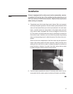
11. Attach your warm water return piping to the inlet connection of the
tower.
Fasteners and components provided by others that are to be attached
to the tower must be compatible with the cooling tower materials—e.g.
fasteners in a stainless steel cold water basin must be stainless steel.
Except for the horizontal components of piping, do not support your
pipe from the tower inlet connection—support it externally.
Normally, one of the following two inlet arrangements is provided:
Bevel and groove distribution connection: This is a factory-installed,
galvanized pipe nipple, extending horizontally from the side of the tower.
It is both beveled for welding—and grooved for a mechanical coupling.
If a weld connection is used, it is recommended that the weld area be
protected against corrosion. Cold galvanizing is suggested, applied
according to the manufacturer’s instructions.
Flanged distribution connection: The spray system is tted with a
at-face ange connection that conforms to 125# ANSI B16.1 speci-
cations. A full faced gasket and appropriately sized bolts (by others)
must be used for proper distribution function.
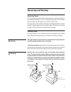
12. Wire motor in accordance with wiring diagram.
For maintenance/safety purposes, SPX recommends a lockout type
disconnect switch for all mechanical equipment. In addition to a
disconnect switch, the motor should be wired to main power supply
through short circuit protection, and a magnetic starter with overload
protection.
Warning
Note
Installation
Caution