


Page 8
GB100W NATURAL OR PROPANE BOILER
INSTALLATION AND OPERATING INSTRUCTIONS
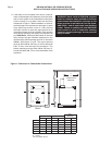
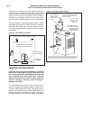
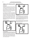
Fasten the vent damper to the flue collar and vent pipe
using at least 3 corrosion resistant sheet metal screws
per joint. Connect the damper harness to the top panel
with the BX connector supplied. Plug the Molex
connector on the damper harness into the mating plug
on the harness located inside the control compartment.
The vent damper is operating properly when it opens
completely upon a call for heat and closes completely
when the call for heat ends. The vent damper must be
in the open position when the boilers main burners are
in operation.
Figure 3: Vent Damper Location
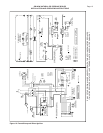
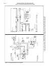
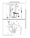
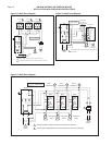
HEATING SYSTEM PIPING
CAUTION: All piping must be installed by a qualified
technician in accordance with the provisions set
forth in the applicable ANSI/ASME standards and
local building codes and regulations. Improper
piping of this boiler can cause flooding, extensive
property damage, heating system damage or
damage to the boiler.
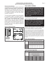
The GB100W hot water boiler comes from the factory
ready to be piped to the heating system. Each boiler is
equipped with a safety relief valve. This valve must be
piped in accordance with the ANSI/ASME Boiler and
Pressure Vessel Code, Section IV. Figure 4 provides a
pictorial description of the boiler and piping components.
Figure 4: Heating System Piping
FRONT OF
BOILER
DAMPER BLADE POSITIONED
FRONT TO BACK OF BOILER
MOTOR TO FACE
FRONT OF BOILER
DISCHARGE PIPE
SIZE TO EQUAL
VALVE OUTLET.
DO NOT RESTRICT
FLOW.
SUPPORT DISCHARGE PIPING
SO AS TO AVOID STRAIN ON
THE VALVE BODY.
DISCHARGE SO AS TO AVOID EXPOSURE OF PERSONS TO
HOT LIQUID OR VAPOR. LEAVE OPEN END VISIBLE FOR
PERIODIC INSPECTION FOR SLOW LEAKAGE OR DRIPS.
1" CLEARANCE MUST BE
MAINTAINED BETWEEN
HOT WATER PIPING
AND COMBUSTIBLE
CONSTRUCTION.
FOR DISCHARGE
THROUGH ROOF
CONSULT THE
SMITH CO.