


Page 5
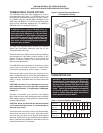
GB100W NATURAL OR PROPANE BOILER
INSTALLATION AND OPERATING INSTRUCTIONS
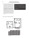
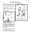
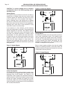
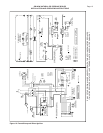
Figure 2: Special Base Installation on
Combustible Flooring
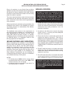
COMBUSTION AIR
WARNING: This boiler must be supplied with
combustion air in accordance with Section 5.3,
Air for Combustion & Ventilation, of the latest
revision of the National Fuel Gas Code, ANSI
Z223.1/NFPA 54 and all applicable local building
codes. Failure to provide adequate combustion
air for this appliance can result in excessive
levels of carbon monoxide which can result in
severe personal injury or death!
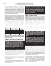
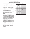
Table 1: Vent and Chimney Dimensions
Boiler Size
3456789101112
(Sections)
Vent Pipe
5566778899
Dia. (In.)
Chimney
8 x 8 8 x 12
Flue Size
Chimney
18 18 18 17 17 17 16 16 16 16
Height (Ft.)
COMBUSTIBLE FLOOR OPTION
The GB100W boiler has been designed for use on
noncombustible floors only. If a GB100W boiler is to
be installed on combustible flooring of any type, it MUST
be installed using the Special Base designed by the
Smith Cast Iron Boiler Co. Do NOT use any base other
than the one specifically designed for it if installing a
GB100W boiler on combustible flooring.
WARNING: Never install a GB100W boiler on
combustible flooring without using the special
base specifically designed for it by the Smith
Cast Iron Boiler Co. Do not alter in any way the
special base supplied by the Smith Cast Iron
Boiler Co. Failure to comply with this warning
may result in a fire causing property damage,
personal injury or death!
To order the Special Base contact the nearest
Smith Cast Iron Boiler distributor and ask for the
“Noncombustible Floor Pan”.
Determine where the boiler will be located by following
the instructions in the Boiler Location section of this
manual. Place the Special Base in this location and
fasten it in place to prevent it from moving while the
boiler is being placed on it.
If the GB100W is being installed in an alcove or closet
ensure that the minimum distance to combustible
construction requirements, listed in Figure 1, are met.
Remove the sheet metal base pan attached to the
boiler. Position the boiler in front of the Special Base. It’s
suggested that two lengths of 3" pipe the width of the
boiler, or longer, be placed under the boiler base side
panels.
CAUTION: Be careful not to damage the burners,
pilot assembly or any other gas train components
during this procedure. If a component is damaged,
replace it!
Carefully roll the boiler up to the front of the Special
Base. Align the boiler base side panels with the Special
Base support channels. Using great care, slide the boiler
onto the Special Base.
CAUTION: Never lift the boiler by the jacket panels
or flue collector/draft diverter or severe damage to
the boiler may result!
Center the boiler from side to side on the Special Base.
Ensure that the back of the burner base side panels
are flush with the back of the Special Base support
channels. Install the front grill supplied with the Special
Base. Complete the installation in accordance with the
instructions set forth in this manual.
FRONT
GRILL
SUPPORT
CHANNEL