


Page 23
GB100W NATURAL OR PROPANE BOILER
INSTALLATION AND OPERATING INSTRUCTIONS
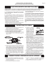
Gas Pressure Adjustment
NATURAL GAS: Optimum results are obtained when
the boiler is operated at its full input rating, with 3.5 in,
89 mm
, WC of manifold pressure. The manifold
pressure should not be more that 5% off this value. The
gas valve pressure regulator has been preset at the
factory. If adjustment is necessary the following steps
must be followed:
1. Attach a manometer to the pressure tap on the gas
valve body.
2. Remove the regulator adjustment screw cap from
the gas valve body.
3. Rotate the regulator adjustment screw clockwise to
increase the manifold pressure, counterclockwise to
decrease it.
4. Replace the regulator adjustment screw cap and
pressure tap plug.
CAUTION: Never force the regulator adjustment
screw beyond the stop limits or damage to the gas
valve will occur!
PROPANE GAS: A manifold pressure of 10.0 in,
254 mm
, WC must be maintained for proper operation of
the boiler. If the manifold pressure is off by more than
5% adjust it according to steps 1 through 4 above.
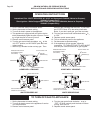
Input Rate
Gas appliances are rated based on sea level operation
with no adjustment required at elevations up to 2000
feet. At elevations above 2000 ft,
610 m
, input ratings
should be reduced by 4% for each 1000 ft,
305 m
above
sea level. Check the input rate as follows:
1. Turn off all other gas appliances that use the same
gas meter as the boiler.
2. Call your gas supplier and ask for the heating
value of the gas.
3. Start the boiler and let it run for 15 minutes.
4. Using the gas meter and a stop watch, clock the
time that it takes to burn 1 cubic foot of gas. To
increase the accuracy of the time, clock the time
that it takes to burn 10 cubic feet of gas and divide
the time by 10.
5. Insert the heating value and the time, in seconds,
into the formula below.
RATE in = HEATING VALUE (BTU/FT
3
) (3600S/HR)
Time (s/ft
3
)
EXAMPLE: If: heating value = 1000 BTU/ft
3
time/ft
3
= 18 s/ft
3
RATE in = (1000 BTU/ft
3
) (3600 s/hr)
18 s/ft
3
RATE in = 200,000 BTU/hr
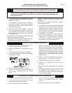
E. With the burners in operation, interrupt the power
to the control circuit by lowering and raising the
thermostat. A normal ignition sequence should follow.
F. To test the ignition safety shutoff device, close the
manual shutoff valve in the gas supply line. Within 6
seconds of main burner flame extinction, the main gas
valve solenoid should close with an audible noise.
On intermittent pilot systems a ticking noise should be
heard while the ignition module tries to relight the pilot.
After 1 minute the module should lockout and the try
for ignition end.
If a direct ignition system is employed, the ignitor should
glow and an attempt at ignition take place. After
unsuccessfully attempting to light the main burners the
ignition module should lock out.
Open the manual shutoff valve in the gas supply line.
Reset the ignition control system by interrupting, then
restoring electrical power to the boiler. A normal
ignition sequence should take place.
BOILER CHECKING & ADJUSTMENT
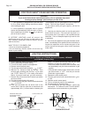
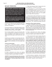
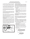
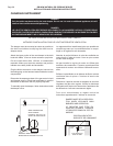
Pilot Adjustment
The pilot burner flame should envelope 3/8 in,
9.5 mm
to 1/2 in, 1
3 mm
, of the thermocouple tip or flame
sensing probe, depending on the pilot type. If the pilot
flame is out of adjustment, remove the cap next to the
pilot tube fitting on the gas valve. Turn the pilot
adjustment screw clockwise to decrease the flame,
counterclockwise to increase it. Figure 18 depicts a
constant pilot, but the adjustment dimensions for an
intermittent pilot would be the same.
Figure 18: Pilot Location
PILOT
BRACKET
5/16
±1/16
1"
±1/16
3/8" - 1/2"
FLAME
ON PROBE
BURNER
TUBE