


Page 12
GB100W NATURAL OR PROPANE BOILER
INSTALLATION AND OPERATING INSTRUCTIONS
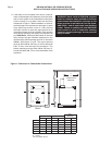
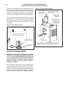
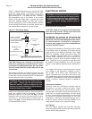
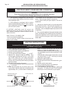
Figure 11 depicts the proper way to connect the boiler
to the gas supply piping. The manual shut-off valve
MUST be installed in the supply piping. It should be
approximately 5 ft,
1.5 m
above the floor. Provide a
drip leg/sediment trap at the bottom of the vertical
section of the gas supply pipe. A ground joint union
should be installed between the boiler gas controls
and the supply piping. Each of these items are needed
to ensure long life and ease of servicing. Always use a
pipe sealant that is suitable for use with LP gas.
Figure 11: Gas Supply Piping
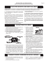
CAUTION: Always use a wrench on the gas valve
body when making gas connections to it. Never
over-tighten the piping entering the gas valve body.
Failure to comply with this caution may result in gas
valve failure!
Safe lighting and other performance criteria were met
with the gas manifold and control assembly provided
on the boiler. All gas connections MUST be leak tested
before putting the boiler into operation.
WARNING: Never use an open flame to test for
gas leaks. Always use an approved leak
detection method. Failure to comply with this
warning can cause extensive property damage,
severe personal injury or death!
Whenever the gas supply piping is pressure tested the
boiler gas controls must be protected. If the test
pressure is equal to, or less than 1/2 psig,
3.5 kPa
,
isolate the boiler by closing it’s manual shut off valve,
see Figure 11. If the test pressure is greater than, or
equal to 1/2 psig,
3.5 kPa
, disconnect the boiler and
it’s individual shut-off valve.
ELECTRICAL WIRING
WARNING: All electrical wiring must conform to
all applicable local codes and the latest revision
of the National Electrical Code, ANSI/NFPA-70.
Failure to comply with this warning can result in
extensive property damage, personal injury or
death!
Electrical Power Connections
CAUTION: Label all wires prior to disconnection
when servicing controls. Wiring errors can cause
improper and dangerous operation!
ATTENTION: Au moment de l'entretien des
commandes, étiquetez tous les fils avant de les
débrancher. Des erreurs de câblage peuvent entraîner
un fonctionnement in-adéquat et dangereux.
S'assurer que l'appareil fonc-tionne adéquatement
une fois l'entretirn terminé.
The electrical connections to this boiler must be made
in accordance with all applicable local codes and the
latest revision of the National Electrical Code, ANSI/
NFPA-70. Installation should also conform with CSA
C22.1 Canadian Electrical Code Part I if installed in
Canada. Install a separate 120 volt 15 amp circuit for
the boiler. A shut-off switch should be located at the
boiler. The boiler must be grounded in accordance with
the authority having jurisdiction, or if none, the latest
revision of the National Electrical Code, ANSI/NFPA-
70.
Line voltage field wiring of controls and other devices
must conform to the temperature limitation of type T
wire at 95°F,
35
°
C
, above room temperature. Use
copper conductors with a minimum size of #14 awg.
Low voltage wiring must not be less than #18 awg with
a neoprene, thermoplastic or other equivalent insulation
having a minimum insulation thickness of 0.012 in,
0.3 mm
.
Thermostat Installation
ALWAYS follow the instructions included with the
thermostat to be used to control the boiler. Proper
location of the thermostat will ensure efficient trouble-
free operation of the boiler. Mount the thermostat to an
inside wall at a height approximately five feet above
the floor. Avoid placing the thermostat in areas that will
not provide an accurate measurement of the room
temperature. Locating the thermostat behind a door, in
an alcove, close to a source of thermal radiation or in a
drafty area will cause poor or sporadic heating.
Vent Damper
The vent damper supplied with the boiler has been
wired with a 6 pin molex connector that will plug directly
into the boiler’s wiring harness.
INSTALL MANUAL
SHUT-OFF VALVE
5 FT. ABOVE FLOOR
WHERE REQUIRED BY
LOCAL CODES
GAS SUPPLY
PIPING
SEDIMENT TRAP
OR
DRIP LEG
(TO EXTEND TO FLOOR)
FLOOR LEVEL
GROUND JOINT
UNION
GAS INLET
TO
BOILER