


Page 6
GB100W NATURAL OR PROPANE BOILER
INSTALLATION AND OPERATING INSTRUCTIONS
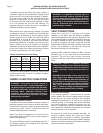
Input Btuh Input Btuh Input Btuh
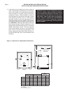
Fresh Air 1/4" Wire Metal Wooden
Duct Size Mesh Screen Louvers Louvers
3" x 12" 144,000 108,000 36,000
8" x 8" 256,000 192,000 64,000
8" x 12" 384,000 288,000 96,000
8-1/2" x 16" 512,000 384,000 128,000
To operate properly and safely this boiler requires a
continuous supply of air for combustion. Oxygen is used
by the burners in the boiler to burn the gas. In addition,
air is also used to assist in the safe disposal of the
products of combustion. This air is known as dilution
air and mixes with the products of combustion to assist
in it’s exit through the flue pipe and chimney. An
adequate supply of outside air must be available to
replace that used by these processes.
Older houses often have enough “leakage” to provide
an adequate amount of combustion air provided that
the demand for combustion air is not too great. Homes
that are relatively new or “tight” will most likely require
the installation of a fresh air duct or other means of
providing air for combustion. Any home utilizing other
gas burning appliances, a fireplace, wood stove or any
type of exhaust fan must be checked for adequate
combustion air when all of these devices are in operation
at one time. Sizing of an outside air duct must be done
to meet the requirements of all such devices.
Table 2: Combustion Air Duct Sizing
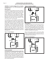
If the boiler will be located in an alcove, closet or any
confined space refer to item 6 in the Boiler Location
section of this manual.
CHIMNEY & VENT PIPE CONNECTIONS
WARNING: This boiler must be vented in
accordance with Part 7, Venting of Equipment, of
the latest revision of the National Fuel Gas code,
ANSI Z223.1/NFPA 54 and all applicable local
building codes. Improper venting of this
appliance can result in excessive levels of
carbon monoxide which can result in severe
personal injury or death!
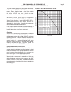
Chimney Inspection & Sizing
If this boiler will be connected to a masonry chimney, a
thorough inspection of the chimney must be performed.
Ensure that the chimney is clean, properly constructed
and properly sized. Table 1 lists the flue size and
chimney height required for this boiler.
When more than one appliance is connected to the
same chimney flue, the flue must be large enough to
handle both appliances.
The vent installation must be in accordance with Part 7
of the latest revision of the National Fuel Gas Code,
ANSI Z223.1/NFPA 54.
WARNING : If an appliance using any type of a
mechanical draft system operating under
positive pressure is connected to a chimney
flue, never connect any other appliances to this
flue. Doing so can result in the accumulation of
carbon monoxide which can cause severe
personal injury or death!
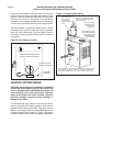
VENT CONNECTIONS
Always use a type B or C vent pipe of the proper
diameter for the boiler. Use the shortest, straightest
vent system possible for the particular application. The
vent system should be sloped up toward the chimney
at a rate of 1/4 in/ft,
2 mm/m
. Ensure that the flue pipe
is properly supported and each connection securely
fastened with at least 3 corrosion resistant sheet metal
screws. The termination of the vent pipe should be
flush with the inside of the chimney flue.
Always provide a minimum clearance of 6 in,
152 mm
,
between type C vent pipe and any combustible
materials. Type B1 vent may be used, clearance
between it and any combustible material must be as
listed.
WARNING: Failure to maintain minimum
clearances between vent connectors and any
combustible material can result in extensive
property damage, severe personal injury or
death!
WARNING: Never modify or alter any part of the
draft hood or vent damper supplied with this
boiler. This includes the removal or alteration of
any baffles in the draft hood or flue collar.
Never install a vent pipe of a diameter different
than that of the boiler draft hood flue collar,
table 1. Failure to comply with this warning can
result in severe personal injury or death.
Common Vent Systems
If an existing appliance is removed from a common
venting system, the common venting system may then
be too large for the proper venting of the remaining
appliances connected to it. At the time of removal of
an existing boiler, the following steps shall be followed
with each appliance remaining connected to the
common venting system placed in operation, while the
other appliances remaining connected to the common
venting system are not in operation.
Au moment du retrait d'une chaudière existante, les
mesures suivantes doivent être prises pour chaque
appareil toujours raccordé au système d'évacuation
commun et qui fonctionne alors que d'autres appareils
toujours raccordés au système d'évacuation ne fonction-
nent pas: système d'évacuation.