


9
ADDITIONAL VENTING REQUIREMENTS: When connecting
to gas vents or chimneys, vent installations shall be in
accordance with Part 7, Venting of Equipment, of the National
Fuel Gas Code, ANSI Z223.1-latest edition, or applicable
provisions of the local building codes.
Vent connectors serving appliances vented by natural draft
shall not be connected into any portion of mechanical draft
systems operating under positive pressure.
When two or more appliances vent into a common flue, the
area of the common flue should be at least equal to the area
of the largest flue plus 50% of the areas of the additional flue
or vent connectors.
When an existing boiler is removed from a common venting
system, common venting system is likely to be too large for
proper venting of appliances remaining connected to it. At time
of removal of existing boiler, following steps shall be followed
with each appliance remaining connected to the common
venting system placed in operation, while other appliances
remaining connected to common venting system are not in
operation:
1. Seal all unused openings in common venting system.
2. Visually inspect the venting system for proper size and
horizontal pitch and determine there is no blockage or
restriction, leakage, corrosion and other deficiencies which
could cause an unsafe condition.
3. Insofar as is practical, close all building doors and windows
and all doors between the space in which the appliances
remaining connected to the common venting system are
located and other spaces of the building. Turn on clothes
dryers and any appliance not connected to the common
venting system. Turn on any exhaust fans, such as range
hoods and bathroom exhausts, so they will operate at
maximum speed. Do not operate a summer exhaust fan. Close
fireplace dampers.
4. Place in operation the appliance being inspected. Follow the
lighting instructions. Adjust thermostat so appliance will
operate continuously.
5. Test for spillage at draft hood relief opening after 5 minutes
of main burner operation. Use the flame of a match or candle,
or smoke from cigarette, cigar or pipe.
6. After it has been determined that each appliance remaining
connected to common venting system properly vents when
tested as outlined above, return doors, windows, exhaust fans,
fireplace dampers and any other gas burning appliance to
previous conditions of use.
7. Any improper operation of the common venting system
should be corrected so installation conforms with the National
Fuel Gas Code, ANSI Z223.1-latest edition. When resizing any
portion of the common venting system, the common venting
system should be resized to approach the minimum size as
determined using the appropriate tables in Appendix G in the
National Fuel Gas Code, ANSI Z223.1-latest edition. For
Canada, the provisions of CAN/CGA B149(.1 or .2) shall apply.
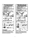
ADDITIONAL CHIMNEY REQUIREMENTS: Chimney
condition is of paramount importance for a safe and efficient
boiler installation. All installations must include a chimney
inspection by a qualified individual or agency. Chimney
construction materials must be compatible with the fuel being
used.
Particular attention should be paid on all oil-to-gas
conversions.Soot may have accumulated in chimney and/or
degraded chimney liner. Most utilities require complete
chimney cleaning. Others may require installation of new liner,
spill switches or other chimney upgrades. Check with local
utility for required safety precautions.
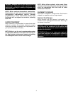
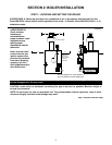
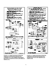
USE VENT SUPPORT(S) AS REQUIRED TO PREVENT SAGGING
MAXIMUM
6 FT.
APART
PITCH 1/4" PER FOOT
SECURE
FLUE PIPE
TO VENT
DAMPER
SINGLE WALL
OR TYPE B
FLUE PIPE
INSTALL
FLUSH
WITH
CHIMNEY
LINER
SEAL
WITH
FURNACE
CEMENT
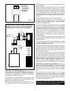
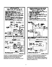
➤PROCEDURE C: Install flue pipe between vent
damper and chimney (6" minimum clearance
required between flue pipe and combustibles).
FIGURE 2.9
DANGER: A chimney which does not meet modern
safety standards will result in a fire or deadly carbon
monoxide poisoning of the building residents.
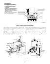
ATTACH LOWER
PORTION OF
VENT DAMPER
TO DRAFTHOOD
OUTLET WITH 1/2"
OR SHORTER
SCREWS OR
POP RIVETS
FIGURE 2.8