


16
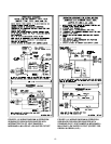
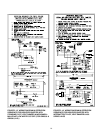
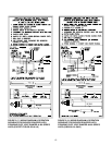
SEQUENCE OF OPERATION
For sequence of operation of the particular boiler being
installed, refer to Figures 2.13 through 2.18 in Section 2
of this manual.
Spill and rollout switches are mounted on Model
GB250-5L, GB250-5H, and GB250-6 boilers.
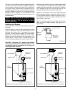
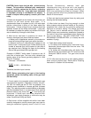
For boilers with a spill switch, the switch detects the
escape of combustion products through the draft
diverter relief opening and interrupts the power to the
gas valve preventing unsafe boiler operation. Escape of
flue products could be caused by a blocked or collapsed
chimney or inadequate chimney draft. This is a manual
reset-type device and can be reactivated by depressing
the spill switch reset button mounted on the left of the
boiler’s draft hood (see Figure 2.1 for switch location).
For boilers with a flame rollout switch, the switch
prevents flame rollout from the boiler combustion
chamber, caused by blocked boiler flue passageways,
by interrupting power to the gas valve to prevent unsafe
boiler operation. This is a manual reset-type device and
can be reactivated by depressing the rollout switch reset
button mounted on the lower front jacket panel. Flue
passages must be inspected by a qualified installer if
this problem occurs, prior to resetting the button.
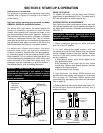
SECTION 3: START-UP & OPERATION
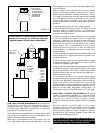
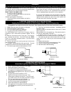
PRESSURE
RELIEF VALVE
WATER
LEVEL
INDICATOR
PRESSURE
CONTROL
PRESSURE
GAUGE
GAS VALVE
FIGURE 3.1
PRIOR TO START-UP
Fill system with water until the water level indicator
(sight glass) is approximately 2/3 full. This water level is
23" from the surface on which the boiler sits.
SYSTEM START-UP & ADJUSTMENTS
Safe lighting and other performance criteria were met
with the gas manifold and control assembly provided on
the boiler when the boiler underwent tests specified in
ANSI Z21.13.
1. Check combination gas valve on boiler and make
sure it is in the OFF position.
2. For vent damper-equipped models, with the
thermostat set to call for heat, observe that vent damper
position indicator rotates to the open position. Damper
must be in the open position when appliance main
burner is operating.
a. After damper opens, spark should appear at the
pilot ignition electrodes.
b.Set thermostat to no longer call for heat. Spark
should stop. Observe that damper position indicator
rotates to the closed position.
c. Set thermostat to call for heat.
3. Light the boiler. For Model GB250 boilers with
standing pilot see lighting instructions for Continuous
Pilot on page 18. For Model GB250 boilers with
intermittent pilot, see lighting instructions for Intermittent
Pilot on page 18.
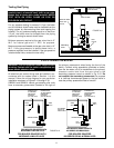
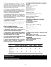
4. Observe pilot and main burner flame (see Figure 3.2).
All burner ports should be ignited and burn with a
steady blue flame.
WARNING: If boiler cannot be restored to normal
operation after re-setting of spill switch, or if flame
rollout switch has tripped, do not attempt to put the
boiler in operation. Immediately contact a qualified
service professional.
WARNING: Keep boiler area clear and free from
combustible materials, gasoline and other
flammable vapors and liquids. Otherwise fire or
explosion may result.
YELLOW
FLAME
(TOO LITTLE AIR)
YELLOW
TIPPING
(MARGINAL)
LIFTING
(TOO MUCH AIR)
NORMAL
(HARD FLAME)
NORMAL PILOT FLAME
MAIN BURNER FLAMES
Q314A/Q309A
CONSTANT PILOT
MODELS
Q3451B
INTERMITTENT
IGNITION PILOT
MODELS
FIGURE 3.2