


6
➤PROCEDURE C:
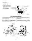
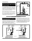
Check component positioning.
1. Remove all packing material
from boiler.
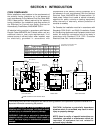
2. Install on non-combustible floor
only, unless local codes permit
use and fabrication of a fireproof
base (see Fig. 2.2).
3. Check that burners and controls
are in the proper position.
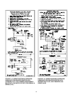
4" HOLLOW CLAY TILE (TWO
COURSES) OPENINGS THRU
BLOCKS IN TOP COURSE TO
BE AT 90 ANGLE TO OPENINGS
THRU BOTTOM COURSE
0
6" OVERHANG OF BLOCK AND
SHEETMETAL ALL AROUND
6"
22 GAUGE
SHEETMETAL
FLOOR
FIGURE 2.2
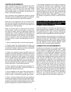
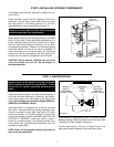
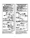
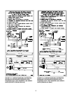
STEP 2: INSTALLING STEAM PIPING
Typical piping connections are shown in Figure 2.3. All
external piping must be supported by hangers, not by
the boiler or its accessories.
Supply outlet must run full size from boiler to a header at
least 24" above top of boiler. Condensate return piping
should be connected to boiler through a "Hartford Loop."
Install gate valves in supply and return.
Proper steam piping practices must be followed at all
times. Maintain proper clearances between piping and
combustible material.
The supply and return lines should be equipped with
drain cocks to drain sediment and sludge from lowest
points of boiler.
FIGURE 2.3
SUPPLY
TAPPING
3" NPT
GATE
VALVE
DRAIN
COCKS
GATE VALVE
RETURN
TAPPING
2" NPT
HARTFORD
LOOP
MUST BE CLOSE
NIPPLE
STEAM
SUPPLY
RETURN
COLD WATER FILL
23-1/4"
WATER LINE
C/L OF HARTFORD
LOOP TO BE 2"
BELOW WATER
LINE
24" MIN.