


CODE COMPLIANCE
Boiler installations must conform to the requirements of
the authority having jurisdiction or, in the absence of
such requirements, to the National Fuel Gas Code ANSI
Z223.1-latest edition. Where required by the authority
having jurisdiction, the installation must also conform to
the Standard for Controls and Safety Devices for
Automatically Fired Boilers, ANSI/ASME CSD-1.
All electrical wiring must be in accordance with National
Electric Code ANSI/NFPA No.70-latest edition and any
additional state or local code requirements. If an
external source is utilized, boiler, when installed, must
be electrically grounded in accordance with
requirements of the authority having jurisdiction or, in
the absence of such requirements, with the National
Electrical Code, ANSI/NFPA No.70-latest edition. UL
listed power limited circuit cable is almost universally
approved for safety controls on heating equipment,
either internally or externally, without protection of
conduits or raceway.
For Canada, the installation must be in accordance with
Standards CGA B149.1 and B149.2 Installation Codes
for Gas Burning Appliances and Equipment and/or local
codes. All electrical connections are to be made in
accordance with Standard C.S.A. C22.1 Canadian
Electrical Code, Part 1 and/or local codes.
2
DANGER: Indicates an imminently hazardous
situation which, if not avoided, will result in death,
serious injury or substantial property damage.
WARNING: Indicates a potentially hazardous
situation which, if not avoided, could result in
death, serious injury or substantial property
damage.
CAUTION: Indicates a potentially hazardous
situation which, if not avoided, may result in minor
injury or property damage.
The following terms are used throughout this manual to bring attention to the presence of potential hazards or to
important information concerning the product:
NOTE: Used to notify of special instructions on
installation, operation or maintenance which are
important to equipment but not related to
personal injury hazards.
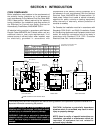
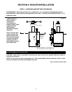
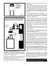
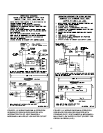
2" RETURN
FRONT
BOILER
MODEL
GB250-S-6
GB250-S-5H
GB250-S-5L
GB250-S-7
DIMENSIONS
A
22 1/2"
22 1/2"
26"
29 1/2"
18"
18"
21 1/2"
25"
B
WATER
LINE
PRESSURE
RELIEF VALVE
ROLLOUT SWITCH
LOW
WATER
CUT-OFF
3/4" PLUGGED
TAPPING
-LEFT SIDE VIEW- -FRONT VIEW- -RIGHT SIDE VIEW-
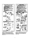
2" RETURN
REAR
FOR MODELS SUPPLIED WITH VENT
DAMPER ADD 3 5/8" TO DIM. E
16 1/2"
3 3/4"
21 7/8"
14 3/4"
2 1/2"
20"
21"
31 1/2"
*E
SPILL SWITCH
8 15/16"
9 3/8"
PRESSURE CONTROL
3"
3" STEAM
SUPPLY
1/2" PLUGGED
TAPPING
23 1/4"
28 1/2"
TRANSF.
115/24V
GAS VALVE
PRESS.
GAUGE
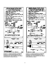
A6 3/4"
18 1/4"
23 1/4"
26 7/8"
C
B
23 7/8"
14 3/4"
2 1/2"
18 1/8"
C
D
E
GB250-S-8
GB250-S-9
29 1/2" 28 1/2"
36 1/2" 32"
10 1/2" 7" 25"
10 1/2" 7" 25"
12 1/2" 8" 30"
14" 8" 30"
15 1/2"
9"
37"
17 1/2" 9" 37"
D
PROBE LOCATION
FOR ELECTRIC
LWCO.
SECTION 1: INTRODUCTION