


8
The flue or vent connectors must be installed flush with
the inside chimney liner surface and sealed in place with
furnace cement. Horizontal portions of the single wall
and type B venting systems shall be supported by use
of strap hangers or their equivalent. Vent supports
should be placed a maximum of 15-feet apart and as
required to prevent sagging. The vent connectors shall
be pitched 1/4" per foot upwards towards the chimney or
vent termination.
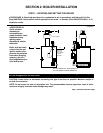
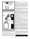
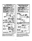
Installing Vent Damper
The vent damper must be mounted directly on top of the
draft hood.
Locate the motor on the front side and position the cable
so that it does not touch the metal surface of the
drafthood (see Figure 2.6). If necessary, turn angle
connector on vent damper upward until cable clears;
tighten locknut to secure.The direction of the flow arrow
imprinted on the vent damper must point upward. The
damper position indicator, which is located on the side
of the vent damper opposite the motor, must be visible.
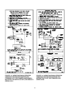
Remove hairpin shipping clip which holds damper blade
in closed position and observe that damper blade
rotates slowly to open position. Do not force it closed as
it may damage the gear train and void the warranty. The
blade should move freely and without obstruction.
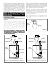
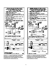
Secure the vent damper housing to the drafthood outlet
with sheet metal screws or pop rivets. Refer to Figure
2.8 for fastener locations. Install flue pipe over top of
vent damper and secure to damper housing with sheet
metal screws or pop rivets.
Attach vent damper cable to cable clamp on boiler left
panel and join the Molex connector (see Figure 2.6 or
Figure 2.6A).
DK. BLUE
THERMOSTAT
CONNECTION
TRANSFORMER
CABLE
BRACKET
DRAFTHOOD
PRESSURE
CONTROL
THERMOSTAT CONNECTION
VENT DAMPER
PILOT CONTROL
FIGURE 2.6: Vent Damper Installation for Intermittent Pilot
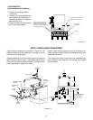
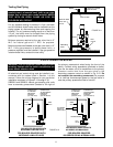
FLOW DIRECTION
ARROW POINTS UP
MOUNT VENT
DAMPER OVER
DRAFTHOOD
MAKE SURE
MOTOR IS
LOCATED ON
FRONT SIDE
FIGURE 2.7
DANGER: Only the boiler may be served by the vent
damper. Do not attempt to use it to vent an
additional appliance. This will cause fire or carbon
monoxide poisoning.
CAUTION: A minimum of 6" between vent damper
and combustible materials must be maintained. The
vent damper must be accessible for servicing and
checking position indicator.
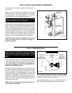
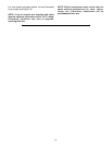
DK. BLUE
THERMOSTAT
CONNECTION
TRANSFORME
R
GAS VALVE
CABLE
BRACKET
DRAFTHOOD
PRESSURE
CONTROL
THERMOSTAT CONNECTION
VENT DAMPER
FIGURE 2.6A: Vent Damper Installation for Standing Pilot