TS2000
TS2000 8 of 20 496529 Issue A
Connect to Control Network
See Fig 6
.
For Mimic. Connect to
CPA6.OM module.
For SAB Tamper.
Link to 0V if not used
Relay contacts are
shown in the
de-energised state.
Alarm relay is normally
energised and is
de-energised at alarm.
Connect
to PIR if
required.
12V supply
present when
system is set
Connect to 3W strobe.
Output will sink up to 250mA
Connect other side to +12V
Connect J3 to JP6 on
Main Board
Fused (F2)
Auxiliary Output
From Internal
SLA Battery
Fuseholder fitted with
1A QB fuse for Network
Power
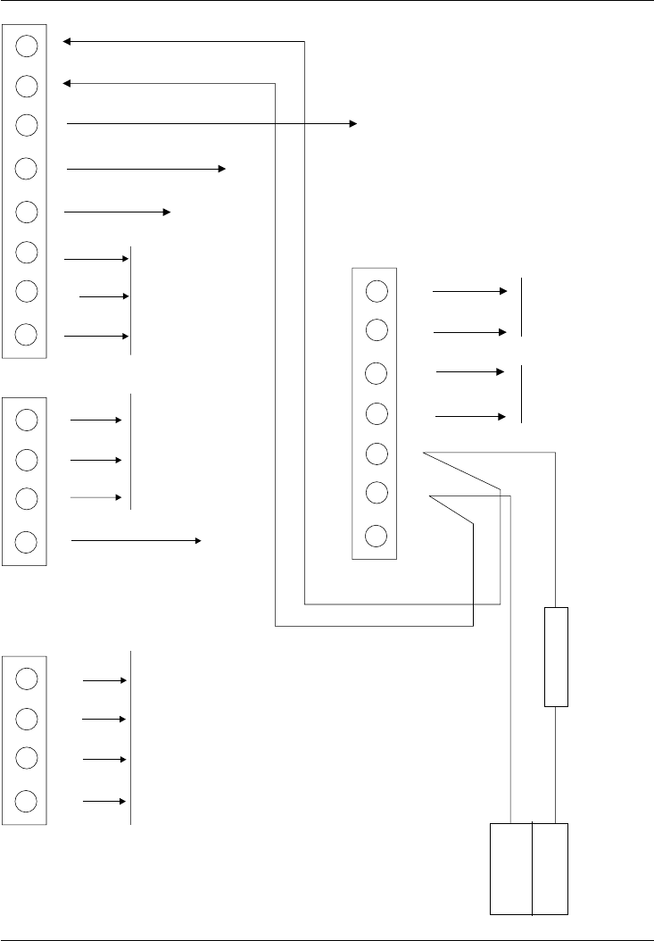
Figure 5. Control Panel Power Supply Unit - Connections
(to the right of the main panel terminals)
Power Supply to
Network ONLY
Fuse F1 on the main board
is not fitted.
INT
+5V
Do not use
INT
0V
INT
+12V
EXT
0V
EXT
12V
BAT
-ve
BAT
+ve
+12V
0V
STRB
WLK TST
NC
C
RELAY
NO
DAT
CLK
LAT
TAMP
DOWN
+
DOWN
-
DIR
+
DIR
-
SW 12
POWER
INPUT
0V
+12V
Figure 4. Control Panel Main Board - Connections
+12V OV


