


TS2000
TS2000 12 of 20 496529 Issue A
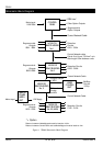
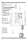
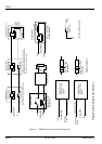
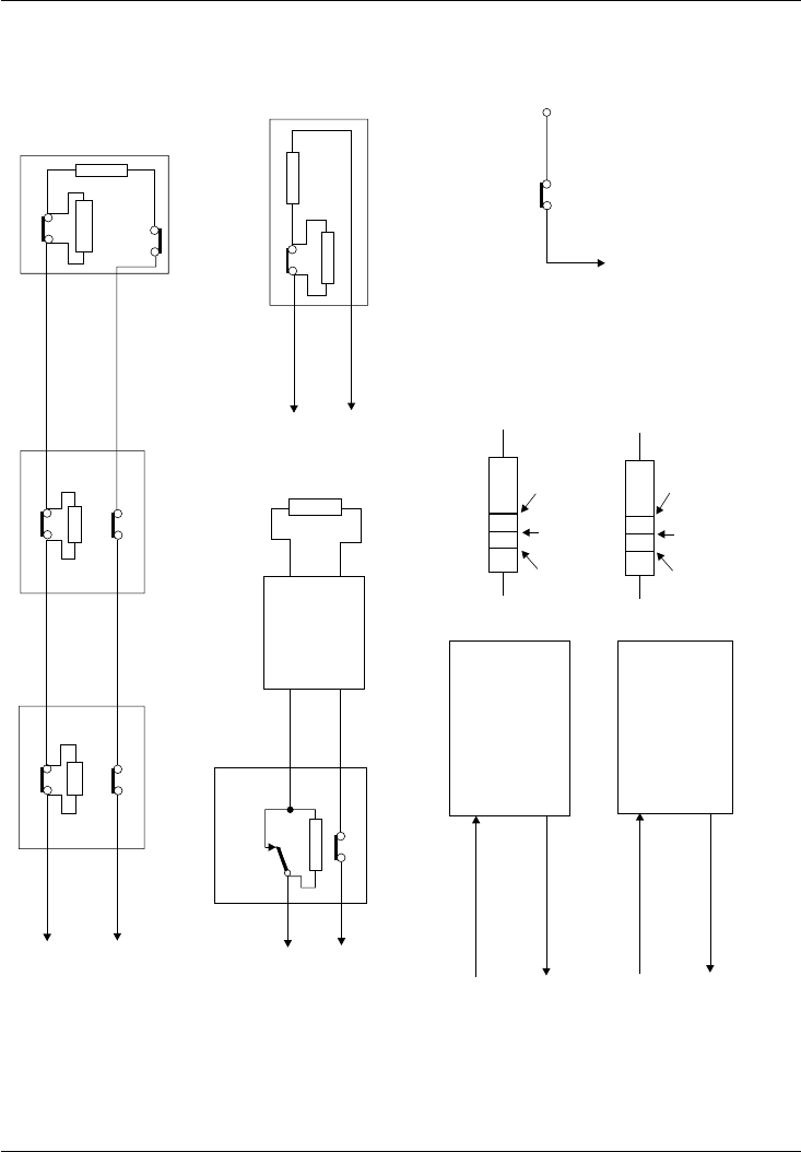
4k7
Tamper Sw
Detector Sw
Next PIR or Det
EOL Res
2k2
Exit Terminator
n.c. (Or n.o.) Contacts
For n.o contacts set
Inverted Attribute
4k7
2k2
E.O.L. Res
X+
I/P X
To Node/REM
Passive Infra Red
(PIR) Detector
X+
I/P X
To Node/REM
Tamper Sw
Detector Sw
EOL
Res
2k2
Tamper Sw
Detector Sw
Tamper Sw
Detector Sw
+
I/P
To Node/REM
Detection Circuit Connections
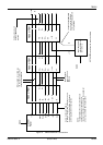
D
e
t
ec
t
or
N
o
1
Detector No2
For PSU monitor circuits connect monitor
lines directly to I/P A or B or C or D and leave
the relevant +ve connection open
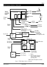
Output Device
Maximum load
100mA
Output Device
Maximum load
100mA
Switched positive
Switched negative
+12V
Sink O/P
CorD
Source O/P
AorB
To Node/REM
To Node/REM
0V
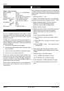
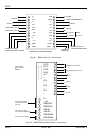
Red Red Red
2k2 Resistor
Yellow Violet Red
4k7 Resistor
Resistor Colours
Tamper
Switch (nc)
0V
Tamp
Box Tamper Connections
Pro
g
rammable Outputs Connections
4k7
4k7
4k7
Detector No n (<11)
Figure 11. TS2000 Circuit and Output Connections