


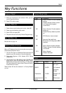

TS2000
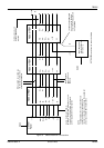
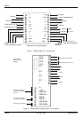
Programmable Ouputs
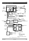
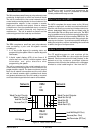
The programmable outputs from the NU and the REM,
arereferredto astheNodeOutputs andareactivatedin
response to various conditions or events. They are
programmed to respond to System, Ward or Circuit
activation.
Panel outputs are from the CP and are programmed in
the same way as the Node outputs. Outputs 1 to 8 are
from the Parallel Interface Board, if fitted, and 9 to 16
are for the DC3 or DC3M Digicom if fitted.
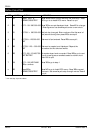
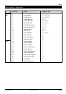
The System activated outputs may be allocated to any
Node (NU or REM) output or the Panel (CP) outputs. They
are designated by their function and may be
programmed to be active if required. The following are
available:
(1) Alarm: A system alarm is present;
(2) P. A.: A Personal Attack circuit or a Duress Alarm
has been activated;
(3) Set: The system is Set;
(4) Fire: A Fire circuit has been activated;
(5) Medical: A Medical circuit has been activated;
(6) Tamper: A Tamper alarm is present;
(7) Aux: An Auxiliary circuit has been activated;
(8) Set Fail: An attempt to set the system has failed;
(9) Site Engr: The Engineer’s passcode has been
entered. The output will remain active until a
User passcode is entered;
(10) Lock-Alarm: The system has not been Set before
the start of the Time Lock period;
(11) Test-Fail: A test failure has occurred;
(12) AC Alarm: The mains supply to the PSU has not
been present for the mains fail time period;
(13) AC Off: The mains supply to the PSU is not
present or there is no 12V output;
(14) Batt Fault: During the PSU test or while the mains
is off the PSU Battery voltage is low.
(15) Bell: The CP bell output is activated;
(16) Strobe: The CP strobe output is activated;
(17) Switch +12: The system is Set and is not in
alarm;
(18) Walk Test +: A Walk Test is in progress (use output
A or B);
(19) Walk Test –: A Walk Test is in progress (use output
C or D);
(20) Line Fault: A Digicom telephone line fault is
present;
(21) Time Switch: The programmed Time Switch is
active;
(22) Time Locked: The system has been Time Locked
and cannot be unset;
(23) Entry Mode: Entry mode has been initiated;
(24) 2nd Entry: The first Entry time has timed out
before a passcode entry
(25) Exit Mode: System Exit procedure has been
initiated;
(26) Exit Setting: Final Exit setting is in progress
(27) Exit Error: An error occurred during the exit
procedure and the system cannot set
(28) Lock Alert: The programmed Time Lock period is
about to start;
(29) Fire/Viper: Will provide 12V (100mA source) to
devices which latch when activated and which
are unlatched when power is removed. The
output is removed for about 3 seconds when
unsetting the system after an alarm at the
second passcode entry;
(30) PSU Test: Connected to remote PSU to initiate a
battery test;
CAUTION: It is essential to ensure that the correct
outputs that willsource (supply) or sink(accept) current
areselected tomatch thefunctionrequired.
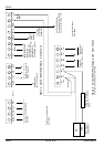
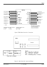
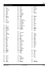
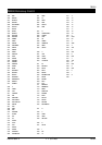
Menus Listing in Sequence
NOTES:
Users will enter menus at Menu 1
Engineer will enter menus at Menu 15
User Level 5 (Standard W) can only set and unset
designated wards
InstantaccesstoMenusfrom akeyboardnumber
entry applies to Menus 1 to 9 only
Menu 2 is only available if a Ward is Set;
Menu 7 is only available if there are circuits with
attribute omit
Menu 9 is only available if a printer is connected
or the SIB is fitted
Menu 17 is only available if a Ward is defined
Menu 24 is only available if a DC3(M) is fitted
Menu 25 is only available if Engineer Reset is
programmed and a reset is required
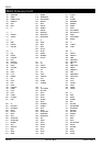
(Passcode) Levels:
1 Engineer
2 Master
3 Manager
4 Standard S
5 Standard W
6 Restricted
TS2000 18 of 20 496529 Issue A