


– 64 –
SM830078
12. SERVICE PROCEDURES
3) Checking the Electrical Parts
11
11
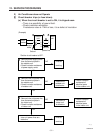
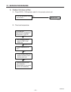
1 Power transformer (TR1) ................. Indoor unit *Measure the coil resistance.
• Primary 230-208 V ; Measure the resistance between two WHT lead wire terminals
of socket connected to power transformer.
• Secondary 10.6 V ; Measure the resistance between two BRN lead wires.
Refer to “1–3–(A) Other component specifications”.
22
22
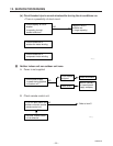
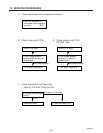
2 Power transformer (TR) ................. Outdoor unit *Measure the coil resistance.
• Primary 230-208 V ; Measure the resistance between two WHT lead wire terminals
of socket jointed to power transformer.
• Secondary 14 V ; Measure the resistance between two BRN lead wires.
Refer to “1–3–(B) Other component specifications”.
33
33
3 Indoor fan motor (FMI) ............... Indoor unit *Measure the coil resistance.
• Measure the resistance between each terminal of the socket connected to the
indoor fan motor.
Refer to “1–2–(A) Major component specifications”.
44
44
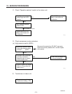
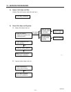
4 Outdoor fan motor (FMO) ........... Outdoor unit *Measure the coil resistance.
• Measure the resistance in the same manner as explained above 3.
Refer to “1–2–(B) Major component specifications”.
55
55
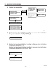
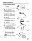
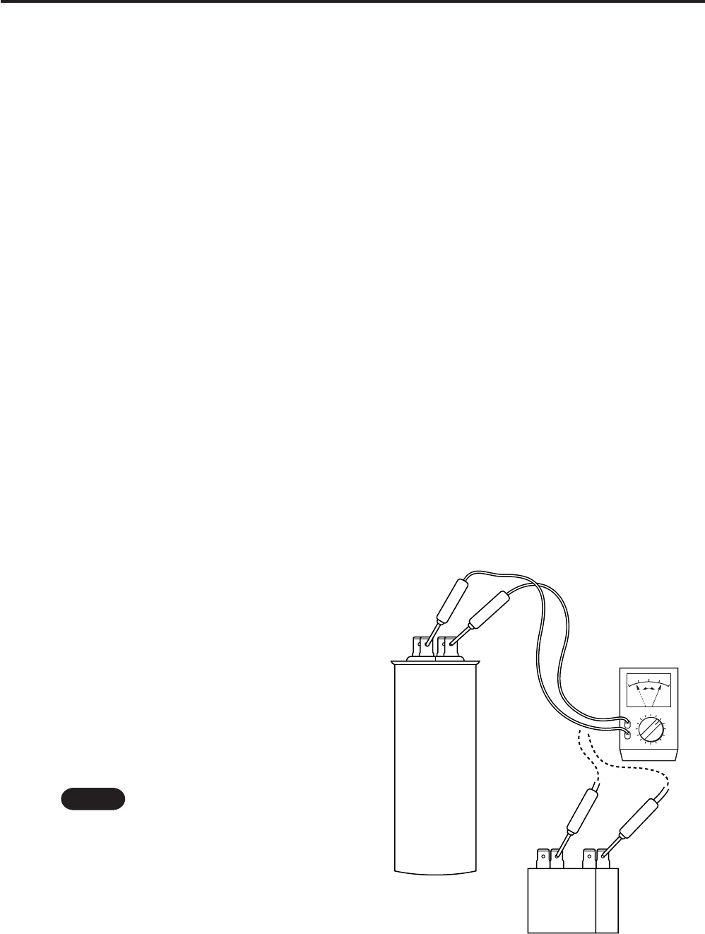
5 Motor capacitor ............ Both in indoor and outdoor unit
• Remove the lead wires from the
capacitor terminals, and then place a
probe on the capacitor terminals as
shown in Fig. 18. Observe the deflec-
tion of the pointer, setting the resis-
tance measuring range of the multim-
eter to the maximum value.
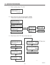
• The capacitor is “good” if the pointer
bounces to a great extent and then
gradually returns to its original posi-
tion.
The range of deflection and the de-
flection time differ according to the
capacity of the capacitor.
Fan motor
capacitor
Compressor motor
capacitor
1041_X_S
Multimeter
Ω
NOTE
Fig. 18