


– 62 –
SM830078
12. SERVICE PROCEDURES
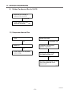
(4) Checking the Electrical Components
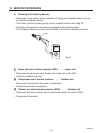
1) Measurement of Insulation
Resistance
• The electrical insulation is acceptable
when the resistance exceeds 1 MΩ.
11
11
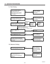
1 Power Supply Wires
Clamp the earthed wire of the Power
Supply wires with a lead clip of the insu-
lation resistance tester and measure the
resistance by placing a probe on either
of the power wires. (Fig. 13)
Then measure the resistance between
the earthed wire and the other power
wires. (Fig. 13)
22
22
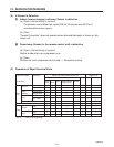
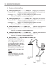
2 Indoor Unit
Clamp an aluminum plate fin or copper
tube with the lead clip of the insulation
resistance tester and measure the
resistance by placing a probe on the
terminal plate (Fig. 14)
33
33
3 Outdoor Unit
Measure the resistance by placing a
probe on the terminal plate in the same
manner as explained above 2. (Fig. 14)
44
44
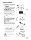
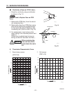
4 Measurement of Insulation Resis-
tance for Electrical parts
• Disconnect the connector of the de-
sired electric part from terminal plate,
P.C.B. Ass’y, etc. (Fig. 15)
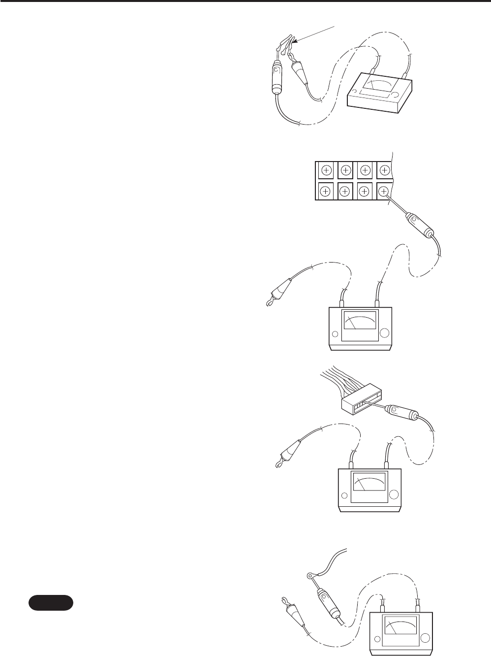
•
Similarly, disconnect the lead wires from
compressor, capacitor, etc. (Fig. 16)
• Measure the resistance in the same
manner as illustrated on the right.
Refer to Electrical Wiring Diagram.
If the probe does not enter the hole be-
cause the
hole is too narrow, use a probe with a
thinner pin.
Fig. 13
Fig. 14
Fig. 15
Fig. 16
Earthed wire
Clip
Probe
Insulation
tester
0638_X_S
Copper
tube or
metallic part
Clip
Insulation
tester
Probe
Terminal plate
0639_X_S
Copper
tube or
metallic part
Clip
Insulation
tester
Probe
0640_X_S
From fan motor,
compressor and other
parts.
Clip
Probe
Insulation
tester
Metallic
part
0641_X_S
NOTE