


17
7. Electrical Wiring
7-1. General Precautions on Wiring
(1) Before wiring, confirm the rated voltage of the unit
as shown on its nameplate, then carry out the wiring
closely following the wiring diagram.
(2) Provide a power outlet to be used exclusively for
each unit, and a power supply disconnect and circuit
breaker for overcurrent protection should be provid-
ed in the exclusive line.
(3) To prevent possible hazards from insulation failure,
the unit must be grounded.
(4) Each wiring connection must be done in accordance
with the wiring system diagram. Wrong wiring may
cause the unit to misoperate or become damaged.
(5) Do not allow wiring to touch the refrigerant tubing,
compressor, or any moving parts of the fan.
(6) Unauthorized changes in the internal wiring can be
very dangerous. The manufacturer will accept no
responsibility for any damage or misoperation that
occurs as a result of such unauthorized changes.
(7) Regulations on wire diameters differ from locality to
locality. For field wiring rules, please refer to your
LOCAL ELECTRICAL CODES before beginning.
You must ensure that installation complies with all
relevant rules and regulations.
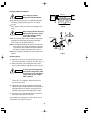
(8) To prevent malfunction of the air conditioner caused
by electrical noise, care must be taken when wiring
as follows:
●
The inter-unit control wiring and the remote con-
trol wiring (option) should be wired apart from the
inter-unit power wiring.
●
It is recommended that shielded wires or twisted-
pair wires be used for the remote control and the
inter-unit control wiring if the air conditioner is
installed where it is exposed to the influence of
electrical and/or electro-magnetic noise.
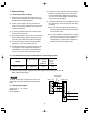
7-2. Recommended Wire Length and Wire Diameter for Power Supply System
Models
Time Delay
Fuse or
Circuit
Capacity
(B)
*1
Inter-unit
Wiring
(A)
*1
Power Supply
AGW #14
C2462R, CL2462R 64 ft. (AWG #12) 35 A
132 ft.
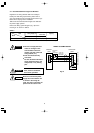
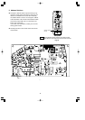
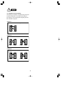
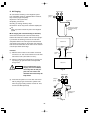
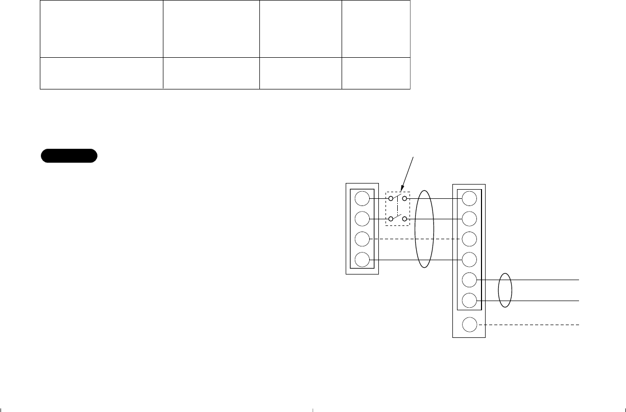
*1 Refer to the Wiring System Diagrams (See below diagram) for the meaning of “A” and “B.”
AWG = American Wire Gauge
1
2
G
4
1
2
4
G
L1
L2
G
Indoor Unit Outdoor Unit
Ground
(B)
(A)
Ground
Disconnect SW
(Field supply)
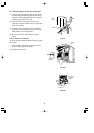
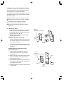
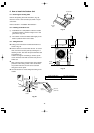
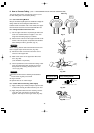
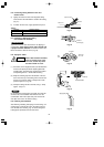
To access the electrical component box, open the air
intake grille and remove the electrical component box
cover.
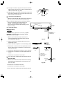
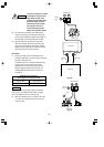
7-3. Wiring System Diagram
Outdoor Unit: “C”, “CL” models
Single-phase
60 Hz, 208/230 V
NOTE