


56
T
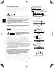
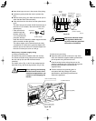
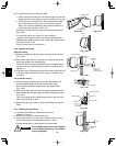
WARNING
It is important that you use
extreme care in supporting
the indoor unit from the ceil-
ing. Ensure that the ceiling
is strong enough to support
the weight of the unit. Before
hanging the ceiling unit, test
the strength of each attached
suspension bolt.
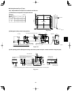
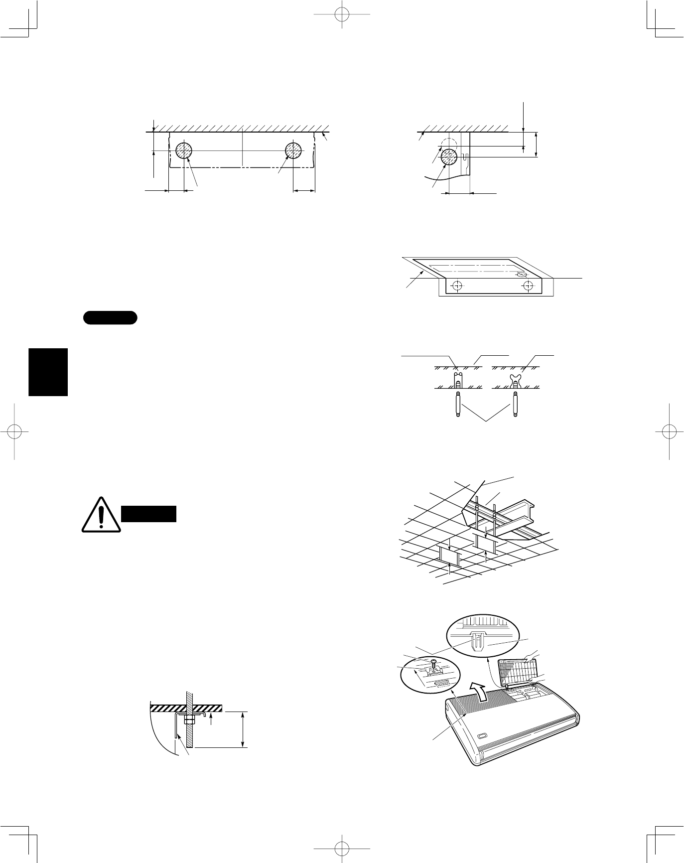
Fig. 3-115
Fig. 3-116
Ceiling tiles
Ceiling suppor t
A
A
unit
Ceiling
surface
Fixture
Within
1-15/16"
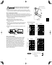
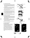
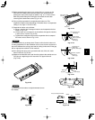
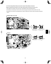
Fig. 3-117
Slide
Hinge
Air-intake grille
Pull out the
air-intake grille
pushing claws
of the hinges
Screw
Latch
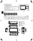
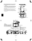
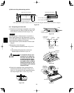
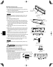
(4) Wall and ceiling side opening position
3-35/64
5-45/64
5-5/16
4-59/64
6-7/64
*
3-35/64
ø3-15/16 wall side opening
ø3-15/16 ceiling opening
ø3-15/16 ceiling opening
Ceiling
ø3-15/16 wall side opening
(for left-side drain hose)
Figure shows view from front
Wall
Figure shows view from top
Full-scale
installation diagram
Wall
Ceiling
Fig. 3-113
Fig. 3-112
Fig. 3-114
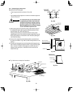
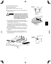
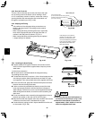
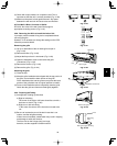
3-31. Suspending the Indoor Unit
(1) Place the full-scale diagram (supplied) on the ceiling
at the spot where you want to install the indoor unit.
Use a pencil to mark the drill holes. (Fig. 3-113).
NOTE
Since the diagram is made of paper, it may shrink or
stretch slightly because of high temperature or humid-
ity. For this reason, before drilling the holes maintain the
correct dimensions between the markings.
(2) Drill holes at the 4 points indicated on the full-scale
diagram.
(3) Depending on the ceiling type:
a) Insert suspension bolts as shown in Fig. 3-114.
or
b) Use existing ceiling supports or construct a
suitable support as shown in Fig. 3-115.
Hole-in-anchor
Hole-in-plug
Concrete Insert
Suspension bolt (M10 or 3/8")
(field supply)
* If the optional drain up kit is installed, create a ø3-15/16" hole along the dotted line (part marked with * in figure).
(4) Screw in the suspension bolts, allowing them to
protrude from the ceiling as shown in Figs. 3-114
and 3-115. The distance of each exposed bolt must
be of equal length within 1-15/16". (Fig. 3-116)