


35
XM
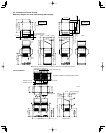
■ 4-Way Air Discharge Semi-Concealed Type (XM
Type)
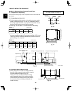
3-8. Preparation for Suspending
This unit uses a drain pump. Use a carpenter’s level to check
that the unit is level.
3-9. Suspending the Indoor Unit
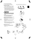
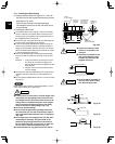
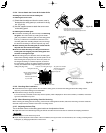
(1) Fix the suspension bolts securely in the ceiling using
the method shown in the diagrams, by attaching
them to the ceiling support structure, or by any other
method that ensures that the unit will be securely
and safely suspended. (Fig. 3-29)
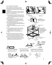
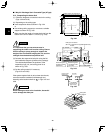
(2) Follow the diagram to make the holes in the ceiling.
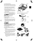
(3) Determine the pitch of the suspension bolts using
the supplied full-scale installation diagram. The dia-
gram shows the relationship between the positions
of the suspension fitting, unit, and panel. (Fig. 3-30)
Hole-in-anchor
Hole-in-plug
Concrete Insert
Suspension bolt (M10 or 3/8")
(field supply)
Nuts and washers
(used for upper and lower)
Double nut
Notch
Suspension lug
Suspension bolt
33/64" – 45/64"
Over 19/32"
Supplied bolt
Full-scale installation diagram
(printed on top of container box)
33/64" – 45/64"
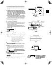
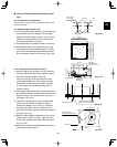
3-10. Placing the Unit Inside the Ceiling
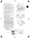
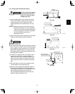
(1) When placing the unit inside the ceiling, determine
the pitch of the suspension bolts using the supplied
full-scale installation diagram. (Fig. 3-31)
Tubing and wiring must be laid inside the ceiling
when suspending the unit. If the ceiling is already
constructed, lay the tubing and wiring into position
for connection to the unit before placing the unit
inside the ceiling.
(2) The length of suspension bolts must be appropriate
for a distance between the bottom of the bolt and the
bottom of the unit of more than 19/32" as shown in
the diagram. (Fig. 3-31)
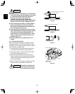
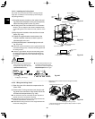
(3) Thread the 3 hexagonal nuts and 2 washers (field
supply) onto each of the 4 suspension bolts as
shown in the diagram. Use 1 nut and 1 washer for
the upper side, and 2 nuts and 1 washer for the
lower side, so that the unit will not fall off the suspen-
sion lugs. (Fig. 3-32)
(4) Adjust so that the distance between the unit and the
ceiling bottom is 33/64" to 45/64". Tighten the nuts
on the upper side and lower side of the suspension
lug. (Fig. 3-32)
(5) Remove the protective polyethylene used to protect
the fan parts during transport.
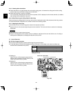
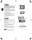
23-5/8"
Ceiling opening dimensions
21-1/32"
Suspension bolt pitch
Drain tube
connection port
(outer dia ø1-1/32")
Refrigerant tubing joint
(liquid side)
ø1/4 (flared)
Power supply port
4-39/64" 1-49/64"
1-49/64"
8-15/32"
11-9/641-3/16"
22-41/64"
6-11/16"6-19/64"
2-3/32"
23-5/8"
Ceiling opening dimensions
21-1/32" Suspension bolt pitch
Fig. 3-29
Fig. 3-30
Fig. 3-31
Fig. 3-32