


39
XM
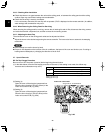
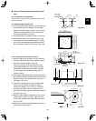
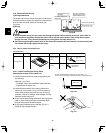
3-13-5. Checking After Installation
●
Check that there are no gaps between the unit and the ceiling panel, or between the ceiling panel and the ceiling surface.
Gaps may cause water leakage and condensation.
●
Check that the wiring is securely connected.
If it is not securely connected, the auto flap will not operate. (“P09” is displayed on the remote controller.) In addition, water leak-
age and condensation may occur.
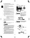
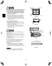
3-13-6. When Removing the Ceiling Panel for Servicing
When removing the ceiling panel for servicing, remove the air-intake grille and air filter, disconnect the wiring connector inside the
electrical component box, and then remove the 4 mounting screws.
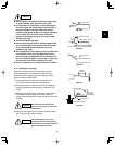
3-13-7. Adjusting the Auto Flap
The air-direction louver on the ceiling panel outlet can be adjusted as follows.
●
Adjust the louver to the desired angle using the remote controller. The louver also has an automatic air-sweeping mechanism.
NOTE
●
Never attempt to move the louver by hand.
●
Proper air flow depends on the location of the air conditioner, the layout of the room and furniture, etc. If cooling or heating seems
inadequate, try changing the direction of the air flow.
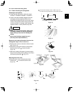
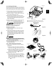
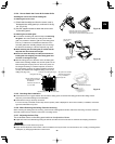
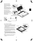
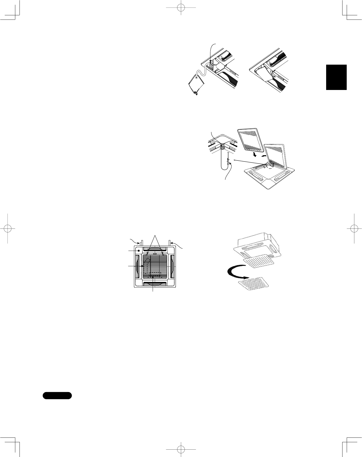
3-13-4. How to Attach the Corner & Air-Intake Grille
Attaching the corner cover and air-intake grille
A. Attaching the corner cover
(1) Check that the safety cord from the corner cover is
fastened to the ceiling panel pin, as shown in the fig-
ure. (Fig. 3-49)
(2) Use the supplied screws to attach the corner cover
to the ceiling panel.
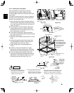
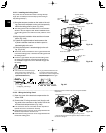
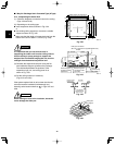
B. Attaching the air-intake grille
●
To install the air-intake grille, follow the steps for Removing
the grille in the reverse order. By rotating the air-intake
grille, it is possible to attach the grille onto the ceiling panel
from any of 4 directions. Coordinate the directions of the
air-intake grilles when installing multiple units, and change
the directions according to customer requests. (Fig. 3-50)
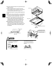
●
When attaching the air-intake grille, be careful that the
flap lead wire does not become caught.
●
Be sure to attach the safety cord that prevents the air-
intake grille from dropping off to the ceiling panel unit
as shown in the figure at right.
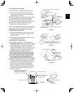
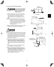
●
With this ceiling panel, the directions of the air-intake grille
lattices when installing multiple units, and the position of the
label showing the company name on the corner panel, can
be changed according to customer requests, as shown in
the figure below. However, the optional wireless receiver kit
can only be installed at the refrigerant-tubing corner of the
ceiling unit. (Fig. 3-51)
Place the corner cover so that the 3 tabs
fit into the holes in the ceiling panel.
Then fasten it in place with the supplied screws.
Pin
Hole for ceiling
panel hook
Hook that prevents
the grille from
dropping
Locations of air-intake grille hinges
Refrigerant tube side
Optional wireless receiver kit
* Only this area is possible
for installation.
Electrical component box
for power PCB
Electrical component box for control PCB
* The grille can be installed
with these hinges facing
in any of 4 directions.
Drain pipe side
Can be installed rotated 90°
Fig. 3-49
Fig. 3-50
Fig. 3-51