


10
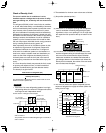
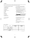
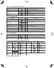
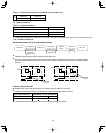
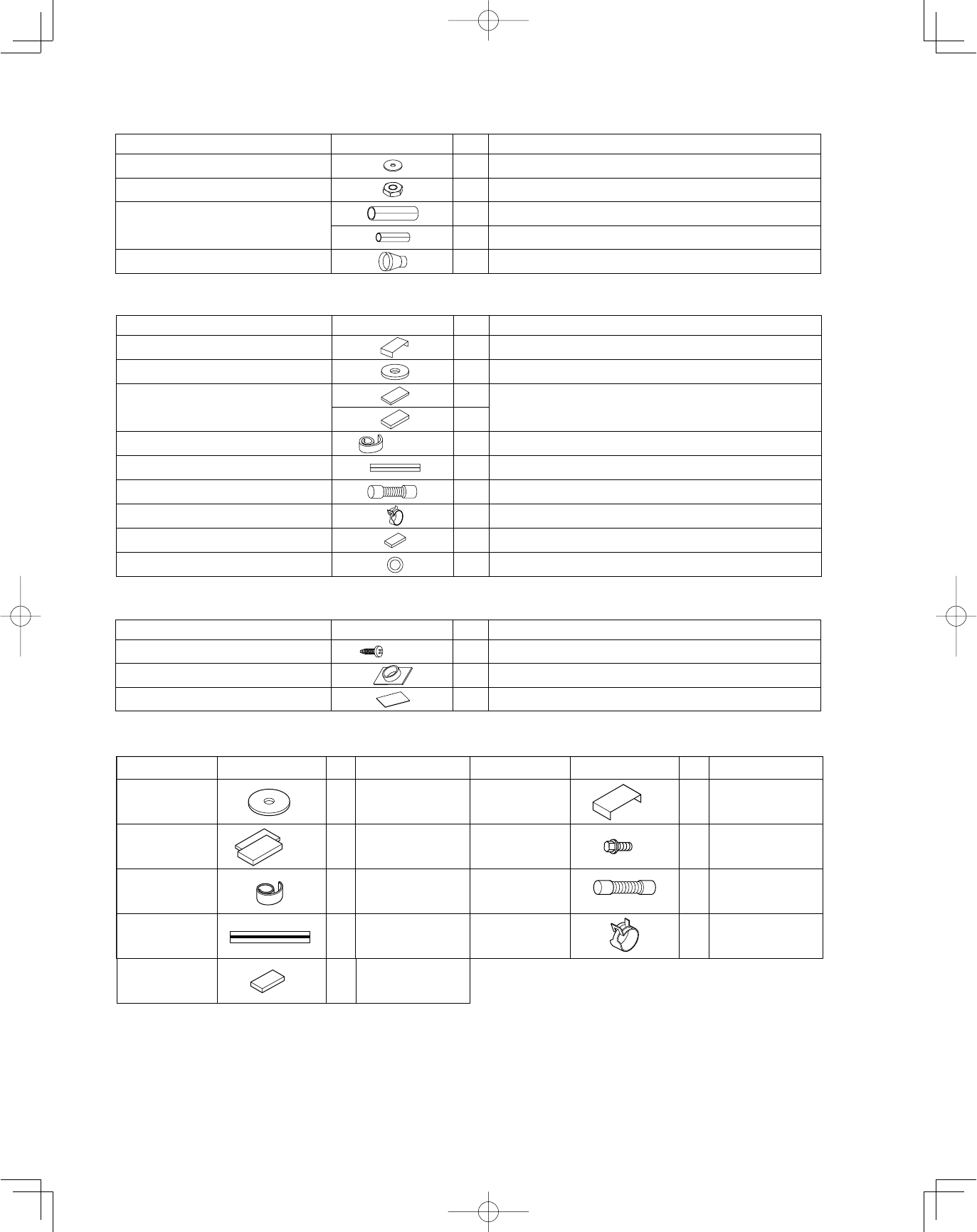
Table 1-5 (Concealed Duct High-Static Pressure)
Table 1-6 (Ceiling-Mounted)
Part Name Figure
Q’ty
Remarks
8 For suspending indoor unit from ceiling Washer
8 For suspending indoor unit from ceiling Nut
1 For gas tube
Flare insulator
1 For liquid tube
1 For drain pipe connection Drain socket
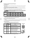
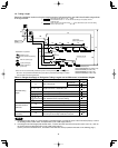
Part Name Figure
Q’ty
Remarks
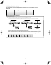
Full-scale installation diagram 1 Printed on container box
Washer 4 For temporarily suspending indoor unit from ceiling
2
For gas and liquid tube joints Flare insulator
2
Insulating tape 2 For gas and liquid tubes flare nuts
Vinyl clamp 8 For flare and drain insulators
Drain insulator 1 For drain hose joint
Gum eyelet 2 For power supply inlet and 3 way wiring
inlet
Drain hose 1 For main unit and PVC pipe joints
Hose band 2 For drain hose connection
L5-1/2"
T3/16"
T1/8"
White
(heat-resisting)
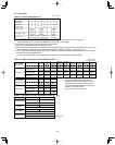
Table 1-7 (Wall-Mounted)
5/32" s 1"
Part Name Figure
Q’ty
Remarks
10 For fixing the rear panel Tapping screw
1 For improved tubing appearance Plastic cover
1 For insulating flare nut (2452 type only) Insulator
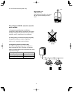
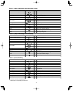
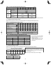
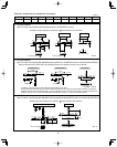
Table 1-8 (4-Way Air Discharge Semi-Concealed) (XM Type)
For temporarily
suspending indoor
unit from ceiling
Flare
insulation
For gas /
liquid tube
connection
Printed on
container box
For gas /
liquid tube / flare
nut connection
For flare / drain
insulating
connection
For unit & PVC
tube connection
For drain hose
connection
For drain tube
connection
Insulation tie
Vinyl tie
Drain hose
Drain hose
insulation
Full-scale
installation
diagram
T10
L140
T3
T5
Hose band
Washer
Parts Name Figure RemarksQ'ty
Parts Name Figure RemarksQ'ty
8
2
set
1
2
8
1
2
1
Washer head
screw
For full-scale
installation
diagram
4
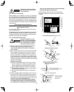
●
Use M10 or 3/8" for suspending bolts.
●
Field supply for suspending bolts and nuts.