


COMBAT
®
CTU UNIT HEATERS INSTALLATION OPERATION AND SERVICE MANUAL
40
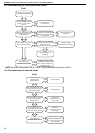
16.6 Ignition Control
IT IS IMPORTANT THAT ONLY THE CORRECT
IGNITION CONTROL SPECIFIED FOR EACH
MODEL TYPE IS USED WHEN REPLACING
THESE ITEMS.
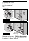
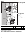
16.6.1 S4565C Models 22 to 60
This control plugs onto the gas valve. Pull out 12 pin
electrical connection. Pull out ignition cable and
flame probe cable noting their positions
Release screw securing control to gas valve
Refit in reverse. Ensure correct location of ignition
and flame probe cables. Ensure that the earth
connection is made directly to the earth point on the
gas valve.
16.6.2 S4563C Models 75 to 115
This control is mounted at the electrical mounting
plate. Pull out the 3 cable connectors.
Pull out ignition cable, ignition earth and flame probe
cable noting their positions. Remove the screws.
Refit in reverse. Ensure correct location of ignition
and flame probe cables.
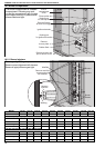
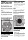
16.7 CTUA Axial Fan/Guard/Motor Assembly
The axial fan unit for the CTUA heater is
supplied completely assembled and balanced.
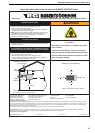
16.7.1 Fan Removal
Remove the four screws
and rubber washers.
Description Part Number
Axial Fan 16 in. 90710418
Axial Fan 500 mm. 90710419
and Replacement
16.7.2 To Replace the Fan Assembly
To replace the fan assembly, reverse the procedure
shown above. Fit rubber washers to the guard
mountings to reduce vibration.
• Check that the fan blades are free to rotate
before turning on the power to the fan.
• Strictly comply with the colour code of the fan
wires to ensure correct operation.
See Page 16,
Section 10.3 through Page 17, Section 10.4 wir-
ing diagrams
• Use only genuine ROBERTS GORDON
®
replacement parts.
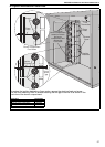
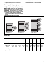
16.8 CTUB & CTUC Centrifugal Fan/Guard/Motor
Assembly
The direct drive fan/s for the CTUB & CTUC range is
supplied as a complete assembly. Take careful note
of the electrical connections of the fan before
disconnecting from the terminals.
For the CTUC versions fitted with an inlet spigot
assembly, the fans may be accessed through the
removable covers on the sides, top and bottom of
the spigot, as required.
16.8.1 Fan Removal and Replacement
20 mm x 5 mm Adhesive Seal
is applied to the flange.
Description Part Number
Torin Fan DDC 270-270 A047
Torin Fan DDC 241-241 A049
Remove the fan by removing the fixing screws while
supporting the weight of the fan (approx. 19 kg).
16.8.2 To Replace the Fan(s)
To reassemble, reverse the procedure shown above.
• Fit new rubber seal between the fan flange and
the heater rear panel.
• Fit to the rear panel in the correct orientation as
shown
on Page 41, Figure 14.
• Strictly comply with the colour code of the fan
wires to ensure correct operation.
See Page 18,
Section 10.5 through Page 20, Section 10.7
wiring diagrams.