


SECTION 16: REMOVAL AND REPLACEMENT PARTS
35
SECTION 16: REMOVAL AND REPLACEMENT PARTS
See warnings and notes on Page 30, Section 13
before removing or replacing parts.
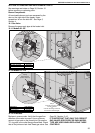
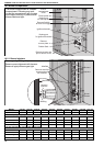
Burner Components
All serviceable burner parts are accessed by the
door on the right side of the heater. Use a
screwdriver to turn the latch 90°.
See Page 5,
Section 4.
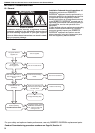
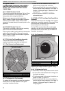
16.1 Gas Valve
Remove the gas supply pipe at the heater inlet.
16.1.1
Disconnect
wire harness
Unplug
control
from
valve
Remove
fixing
screw
Ignition
Control
Description Part Number
Gas Valve VR4105A 90033403
Ignition Control 90434010
Models 22 - 60
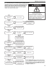
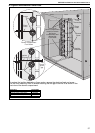
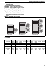
16.1.2
Step 1
Unscrew
gas pipe
from the
valve inlet.
Step 2
Unscrew valve from the
burner manifold
or
unscrew the fixing screws for
the inlet and outlet flanges.
Unplug
electrical lead.
(rectifier harness)
Ignition
Control
Description Part Number
Gas Valve VR4605 90033404
Ignition Control 90434020
Models 75 - 115
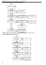
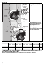
16.1.3 All Models
Replace in reverse order. Verify that the gas flow
direction of the valve is correct. Use a minimum
amount of gas seal on the thread joint. Re-use the
"O" ring seal in the outlet flange where fitted. Check
that all the joints are leak free. Reset gas valve.
See
Page 26, Section 11.4.2.
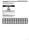
IT IS IMPORTANT THAT ONLY THE CORRECT
GAS VALVES SPECIFIED FOR EACH MODEL
TYPE ARE USED WHEN REPLACING THESE
CONTROLS.