


SECTION 10: WIRING AND ELECTRICAL INFORMATION
17
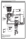
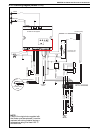
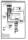
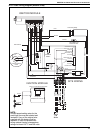
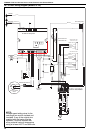
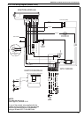
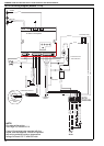
10.4 CTUA Wiring Diagram (Models 75-115)
S 4563 C Honeywell
230 V
1 Ø
50 Hz
SITE WIRING
N L 1 2 3 7 8
REMOTE LOCKOUT RESET
REMOTE LOCKOUT INDICATION
THERMOSTAT
REMOTE FAN ON
LINE
NEUTRAL
GROUND
L
N
E
COMBUSTION FAN
AXIAL FAN
L
N
E
BROWN
RED
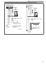
NC\P(2)
Pressure Switch
Detail
NO\P(3)
C \P(1)
BLACK
YELLOW
WHITE
PRESSURE SWITCH
AXIAL FAN
BLUE
PINK
GREY
PURPLE
LOCKOUT
RUN
GREEN/YELLOW
BLACK
WHITE
YELLOW
GREEN/YELLOW
BROWN
BLUE
BROWN
BLUE
BLUE
BROWN
MAINS FILTER
GREEN/YELLOW
BLACK
SENSE
IGNITION
BLACK
BROWN
BLUE
L
N
E
Thermostat Limit
Thermodisc N/C
BROWN
Time Delay Relay
BLUE
BROWN
BROWN
LOCKOUT
RESET
NOTE:
If any of the original wire supplied with
the heater must be replaced, it must be
replaced with wiring material having a
temperature rating of at least 105° C
and 600 volts.