


SECTION 10: WIRING AND ELECTRICAL INFORMATION
19
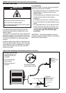
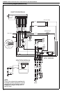
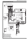
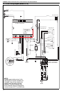
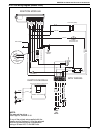
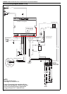
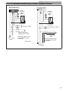
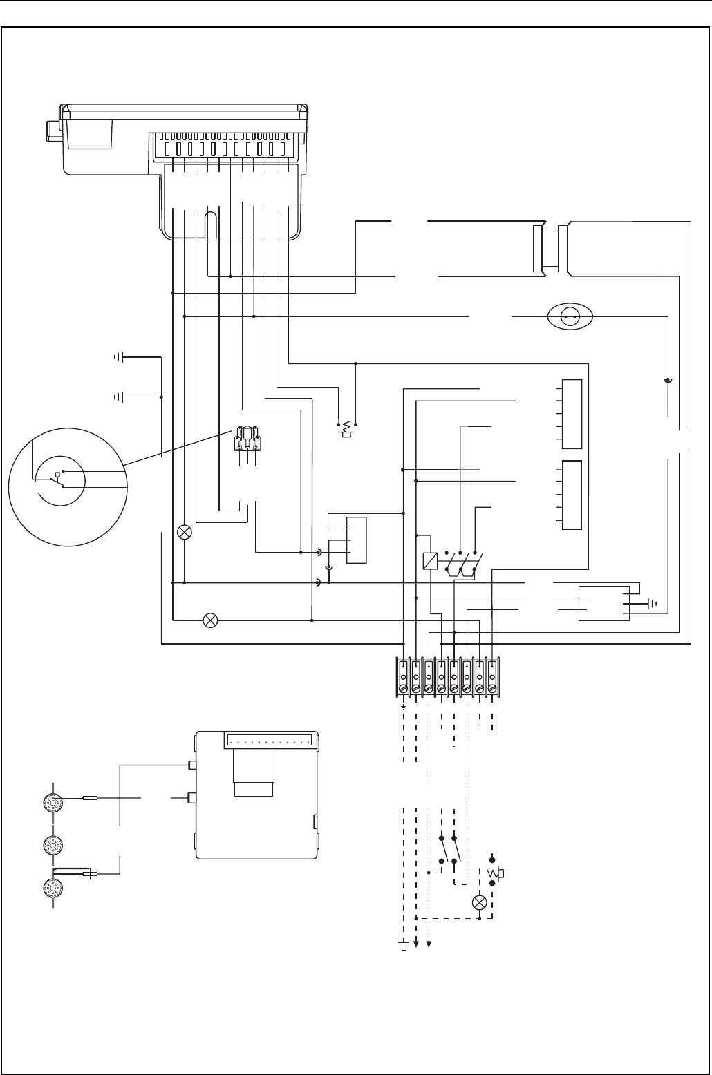
10.6 CTUB/C Wiring Diagram (Models 50-60)
B
7
8
9
A
5
4
6
RELAY
IGNITION MODULE
BLACK
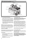
Plug in Connection to Gas Valve
S4565C 1017 Control
Honeywell
BLACK
SENSE
IGNITION
230 V
1 Ø
50 Hz
IGNITION MODULE
LOCKOUT
GAS VALVE
RUN
1112 7910 8 564
SITE WIRING
23 1
N L 1 2 3 7 8
BLUE
BROWN
BLUE
MAINS FILTER
Pressure Switch
Detail
WHITE
YELLOW
BLACK
BROWN
RED
RED
E
N
L
REMOTE LOCKOUT RESET
REMOTE LOCKOUT INDICATION
THERMOSTAT
REMOTE FAN ON
LINE
NEUTRAL
GROUND
YELLOW
BLACK
WHITE
PRESSURE SWITCH
GREEN/YELLOW
BLACK
BROWN
BROWN
BROWN
YELLOW
BLUE
WHITE
PINK
PURPLE
GREY
NO\P(3)
C\P(1)
NC\P(2)
GREEN/YELLOW
WHITE N
LOW RED
HIGH BLACK
MEDIUM BLUE
CENTRIFUGAL FAN 2
CENTRIFUGAL FAN 1
GREEN/YELLOW
WHITE N
LOW RED
HIGH BLACK
MEDIUM BLUE
COMBUSTION
FAN
Thermostat Limit
Thermodisc N/C
BROWN
BLUE
BROWN
Time Delay Relay
LOCKOUT
RESET
NOTE:
Unused speed setting wires for the
centrifugal fan must be isolated and
insulated. If any of the original wire
supplied with the heater must be
replaced, it must be replaced with
wiring material having a temperature
rating of at least 105° C and 600 volts.