


TABLE OF FIGURES
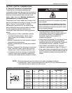
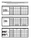
Figure 1: Standard Reflector .....................................................3
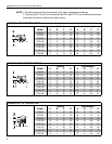
Figure 2: One Side Reflector.....................................................4
Figure 3: Two Side Reflectors ................................................... 4
Figure 4: 45° Tilt Reflector ........................................................4
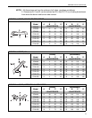
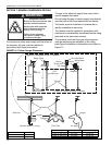
Figure 5: U-Tube, Standard Reflector........................................5
Figure 6: U-Tube, 45°................................................................5
Figure 7: U-Tube, Opposite 45° Reflector .................................5
Figure 8: 2-Foot Deco Grille, 1-Foot Deco Grille and
Protective Grille ..........................................................6
Figure 9: Lower Clearance Shield.............................................6
Figure 10: Venting .....................................................................6
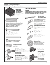
Figure 11: Major Component Descriptions................................9
Figure 12: Critical Hanger Placement ..................................... 10
Figure 13: Linear Heater Assembly Overview......................... 14
Figure 14: Unitary Linear Layout Overviews ...........................15
Figure 15: Unitary Linear Layout Overviews (Continued) ....... 16
Figure 16: U-tube Assembly Overview.................................... 17
Figure 17: Unitary U-Tube Layout Overviews..........................18
Figure 18: Typical CTHN Multiburner System Installation .......29
Figure 19: Flag Layout ............................................................32
Figure 20: Modified In-Series Layout ......................................32
Figure 21: T Layout.................................................................33
Figure 22: Fork Layout ............................................................34
Figure 23: Herringbone Layout................................................35
Figure 24: Reflector Joint Detail..............................................43
Figure 25: Fan Termination .....................................................51
Figure 26: Tailpipe Connection Points.....................................55
Figure 27: Roof Venting of Pump ............................................56
Figure 28: Side Wall Venting Configurations...........................57
Figure 29: General System Control Wiring (Multiburner) ........64
Figure 30: External Wiring Diagram EP-100 and
EP-201 120 V 1 Ø Pump (Multiburner) ..................65
Figure 31: External Wiring Diagram EP-301 230 V 1 Ø Pump
(Multiburner)..........................................................65
Figure 32: External Wiring Diagram EP-203 or
EP-303 3 Ø Pump (Multiburner) ............................66
Figure 33: One Zone Operation without Control Panel
(Multiburner)..........................................................67
Figure 34: Two Zone Operation without Control Panel
(Multiburner)..........................................................68
Figure 35: Gas Connection with Flexible Gas Hose ...............69
Figure 36: Vacuum Differential Reading..................................72