


SECTION 6: MAJOR COMPONENTS
9
SECTION 6: MAJOR COMPONENTS
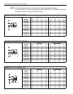
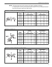
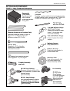
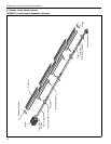
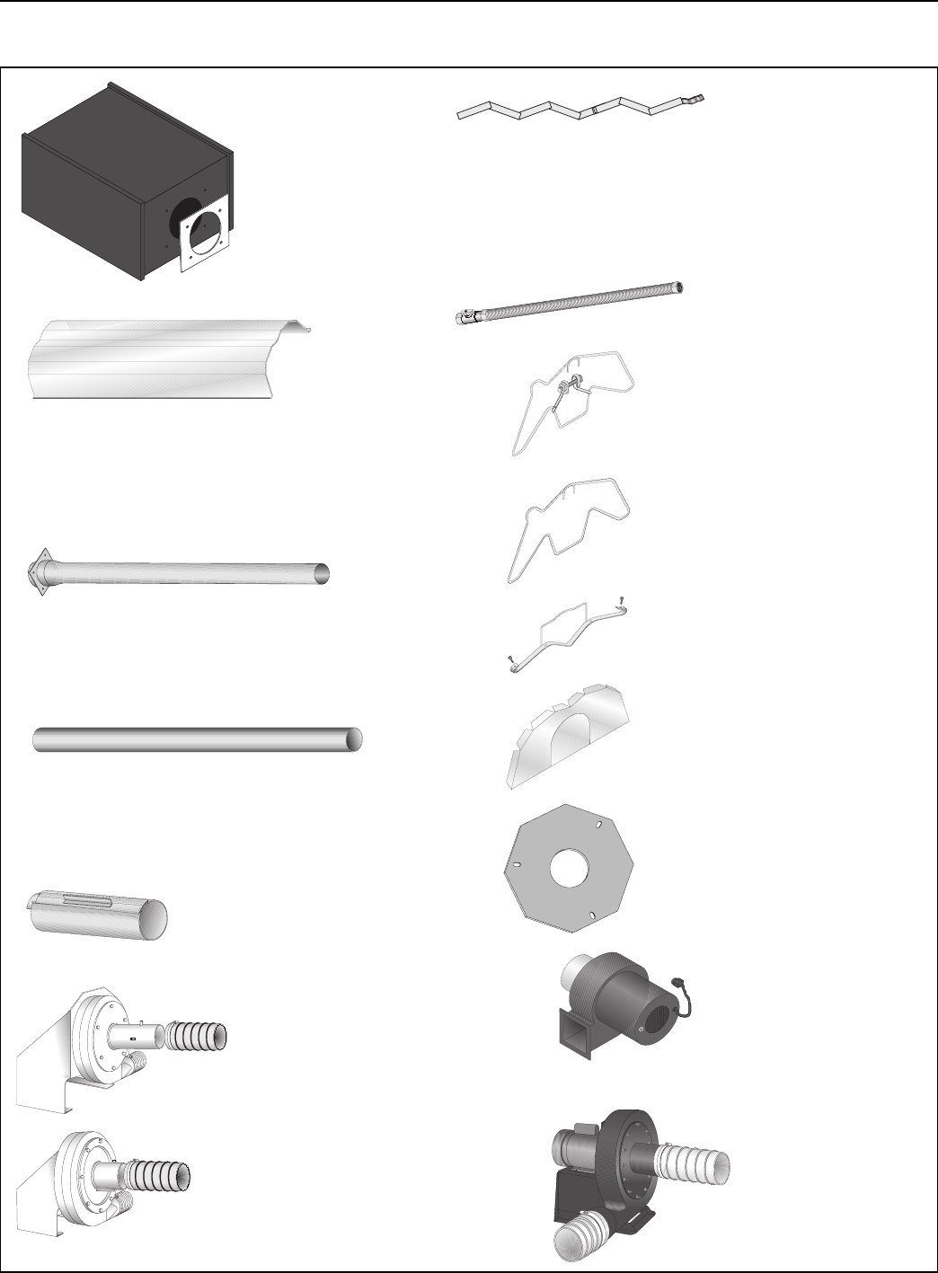
FIGURE 11: Major Component Descriptions
Tube and Reflector Hanger
with Clamp Package
Position this hanger no more
than 4'' (10 cm) away from
the burner assembly.
Coupling Assembly
with Lock
Reflector End Cap
Punch out center section to
accommodate tube.
Tube and Reflector Hanger
Suspend system from these
hangers.
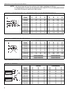
Flex Gas Line
with Shut Off Cock
Burner Tube
Supplied in 10' (3 m) lengths.
Burner tube is always the first
tube after the burner.
Reflector Support
Strap & Wire Form
Turbulator
Turbulator must be installed in the last standard section
of tube.Turbulator is only required on the CTHN-40, 60
and 80. For installation, See Page 21, Step 8.8.
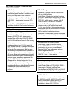
EP-100 Pump Package -
For more information, refer to the
EP-100 Installation, Operation and
Service Manual
(P/N 127201NA).
EP-201 Pump Package -
For more information, refer to
the EP-200 Series Installation,
Operation and Service Manual
(P/N 127200NA).
Fan Assembly
EP-300 Series
Pump Package -
For more information,
refer to the EP-300
Series Installation,
Operation and
Service Manual
(P/N 127202NA).
Reflector (Aluminum or Stainless Steel)
Alternate overlap as shown on Page 15,
Figure 14 or on Page 18, Figure 17.
Minimum overlap is 6'' (16 cm).
Tube
Hot rolled or heat treated aluminized
tube supplied in 10' (3 m) lengths.
Burner with
Tube Gasket
Must be installed
with the flame
observation window
facing down.
Restrictor Plate
Used at fan assembly inlet
for unitary heaters only.
See fan assembly below.