


SECTION 9: MULTIBURNER HEATER INSTALLATION
31
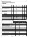
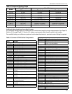
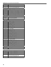
9.4 Radiant Tube Length
The radiant tube length fixed for each burner is
shown on Page 30, Table 10.
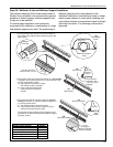
9.5 Manifold Tube
Any tube beyond the radiant tube length is
considered manifold. Manifold tube can be used to
lengthen tube runs beyond the radiant tube length; to
connect multiple runs of tubing and connect the
system to the pump. Minimum and maximum
manifold tube lengths are shown on Page 30,
Ta b l e 10 . The table must be used in conjunction
with the additional rules for the diameter and
length of manifold in a system, as described on
Page 31, Section 9.5.1 through Page 35, Section
9.6.3.
9.5.1 Manifold Diameter
1. Manifold diameter for systems containing less
than 320,000 Btu/h input can be 4" (10 cm) or
6" (15 cm).
2. Manifold diameter for systems containing
320,000 Btu/h input and greater must be 6"
(15 cm).
Exception: If total manifold tube length is 70'
(21 m) or less, 4" (10 cm) diameter manifold
tube can be used for systems up to
800,000 Btu/h.
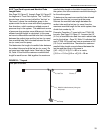
9.6 Multiburner System Layouts and Manifold
Tube Length Rules
Most CTHN multiburner layouts can be classified as
one of the following five layout types:
Flag, Modified In-Series, T, Fork or Herringbone.
Please refer to Page 31, Section 9.6.1 through Page
35, Section 9.6.3 for explanation of manifold rules
and basic diagrams of each layout type. The
diagrams show very simple examples of each layout
type. Actual layouts will vary in total number of
burners in the system as well as the overall shape of
the system. Additional pieces such as elbows may
change the overall layout appearance but are usually
considered a variant of one of the five multiburner
layout types.
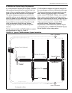
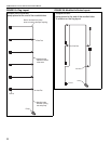
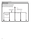
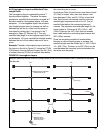
9.6.1 Flag and Modified In-Series Layouts and
Manifold Tube Length Rules
See Page 32, Figure 19 through Page 32, Figure 20
for diagrams of Flag and Modified In-Series layouts.
Minimum and maximum manifold tube length applies
to all tubing between the end of a radiant tube run
and a tee or cross; all tubing between any tees and/
or crosses; and all tubing between the last tee or
cross and the pump. See Page 30, Table 10.
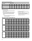
Example: Consider a Flag or Modified In-Series
layout with five CTHN-100 burners. Page 30, Table 10
shows a minimum of 6' (2 m) and a maximum of 45'
(13.5 m) of manifold tube required per burner.
Therefore the entire five-burner system must have
between 30' (10 m) and 225' (69 m) of manifold
tubing. The manifold tubing is in addition to the 40'
(12 m) of radiant tube per burner. Radiant tube may
end at a tee, or runs may be lengthened by adding
some manifold tube between the end of the radiant
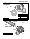
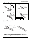
tube and a tee. Each burner in the system (except for
the burner furthest from the pump) must use a
damper coupling to properly adjust the vacuum at
each burner. The damper coupling may be placed
anywhere between the end of the radiant pipe and
the tee.