


CTHN-SERIES INSTALLATION, OPERATION AND SERVICE MANUAL
4
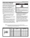
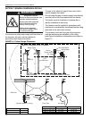
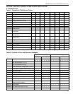
NOTE: 1. All dimensions are from the surfaces of all tubes, couplings and elbows.
2. Clearances B, C and D can be reduced by 50% after 25' (7.5 m) of tubing downstream
from where the burner and burner tube connect.
.
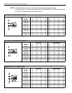
FIGURE 2: ONE SIDE REFLECTOR
(inches) (centimeters)
Model ABCDABCD
CTHN-40 5 6 46 35 13 15 117 88
CTHN-60 5 6 55 44 13 15 140 110
CTHN-80 5 6 64 49 13 15 163 123
CTHN-100 5 6 66 51 13 15 168 128
CTHN-125 5 6 69 58 13 15 175 145
CTHN-150 5 6 75 60 13 15 191 150
CTHN-175 8 6 77 68 20 15 196 170
CTHN-200 8 6 79 70 20 15 201 175
A
C
D
B
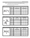
FIGURE 3: TWO SIDE REFLECTORS
(inches) (centimeters)
Model ABCDABCD
CTHN-40 5 16 47 16 13 41 119 41
CTHN-60 5 18 56 18 13 46 142 46
CTHN-80 5 21 65 21 13 53 165 53
CTHN-100 5 23 68 23 13 58 173 58
CTHN-125 5 26 73 26 13 66 185 66
CTHN-150 5 30 76 30 13 76 193 76
CTHN-175 8 32 88 32 20 81 224 81
CTHN-200 8 33 90 33 20 84 229 84
A
C
D
B
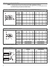
FIGURE 4: 45° TILT REFLECTOR
(inches) (centimeters)
Model ABCDABCD
CTHN-40 8 4 35 43 20 10 89 109
CTHN-60 8 4 45 45 20 10 114 114
CTHN-80 9 4 54 55 23 10 137 140
CTHN-100 10 4 57 56 25 10 145 142
CTHN-125 10 4 63 58 25 10 160 147
CTHN-150 10 4 66 61 25 10 168 155
CTHN-175 10 4 69 68 25 10 175 173
CTHN-200 10 4 73 71 25 10 185 180