


SECTION 9: MULTIBURNER HEATER INSTALLATION
33
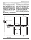
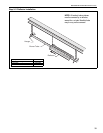
9.6.2 T and Fork Layouts and Manifold Tube
Length Rules
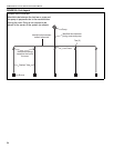
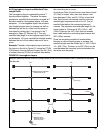
See Page 33, Figure 21 through Page 34, Figure 22
for diagrams of T and Fork layouts. The T and Fork
layouts have a tee or cross (called the "last tee" or
"last cross") where the combustion gases in the
system enter the tee or cross with directly opposing
flow directions, which creates an added source of
pressure drop in the system. This additional source
of pressure drop requires some difference in how the
allowed manifold length is calculated. In this case,
we have to differentiate manifold tube that is located
between the radiant pipe and the last tee (or cross)
from manifold tube that is located between the last
tee (or cross) and the pump.
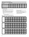
First determine the length of manifold tube between
the radiant tube end and the last tee (or cross). Do
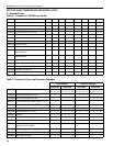
not count any tube length twice. Now refer to Page
30, Table 10 and find the maximum manifold tube
length for each burner. Add together the maximum
manifold tube length on the table for each burner in
the system, this is the maximum manifold tube length
for the entire system.
To determine the maximum manifold tube allowed
between the last tee (or cross) and the pump:
Subtract the manifold tube length between the
radiant tube and the last tee (or cross) from the
maximum manifold length for the entire system, then
divide that number by 1.5.
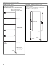
Example: Consider a T layout with two CTHN-100
burners. See Page 33, Figure 21. Assume that 15'
(4.5 m) of manifold was used from each radiant tube
end to the last tee. Page 30, Table 10 indicates that
each CTHN-100 burner can have a maximum of 45'
(13.5 m) of manifold tube. Therefore the maximum
manifold tube length amount allowed between the
last tee and the pump in this case is
([45' + 45']-[15' x 2])/1.5 = 40' or in metric,
([13.5 m + 13.5 m]-[4.5 m x 2])/1.5 = 12 m.
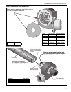
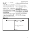
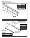
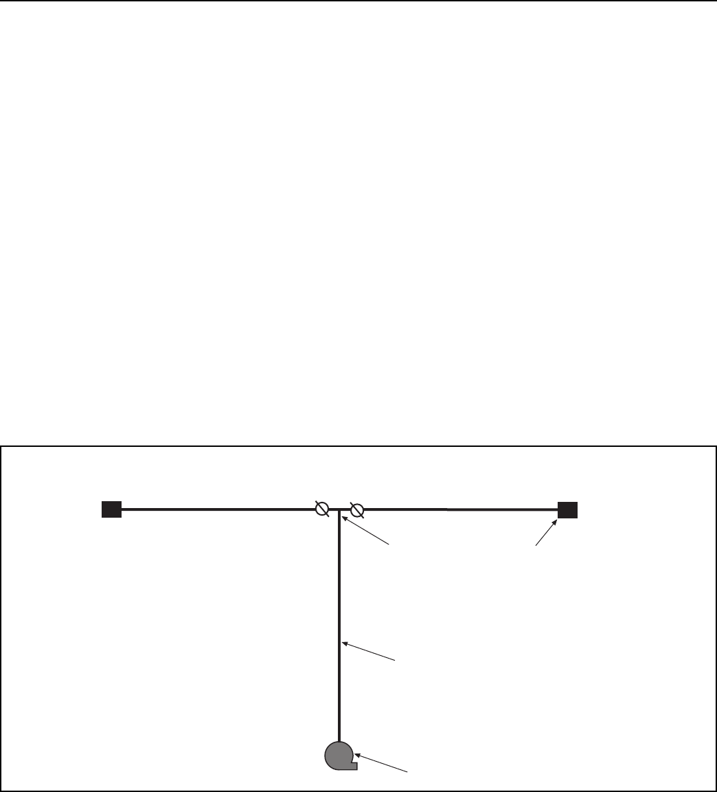
FIGURE 21: T Layout
Pump
Manifold tube between joining tee
and pump.
Last Tee
Burner
One pair of burners.