


ROBERTS GORDON
®
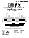
CRV-SERIES SUBMITTAL SHEET
© 2004 Roberts-Gordon
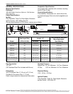
BE FORE INSTAL LATION AND OPERATION OF HEATING EQUIPMENT, READ AND UNDERSTAND T HE INSTALLATION, O PERATION AND SE RVICE MANUAL.
APPLICAT IONS, ENGINEERING AND DETAILED GUIDANCE ON SYSTEMS DESIGN, INSTALLATION AND PRODUCT PERFORMANCE IS AVAILABLE UPO N REQUEST. ROBERTS GORDON
®
PRODUCTS ARE TO BE
INSTALLED ONLY I N ACCORDANCE WITH L OCAL LAWS, CODES AND REGULATIONS, AND ONLY BY A CONTRACTO R QUALIFIED IN THE INSTALLAT ION AND SE RVICE OF GAS-FIRED HEATING EQUIPMEN T.
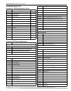
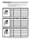
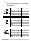
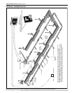
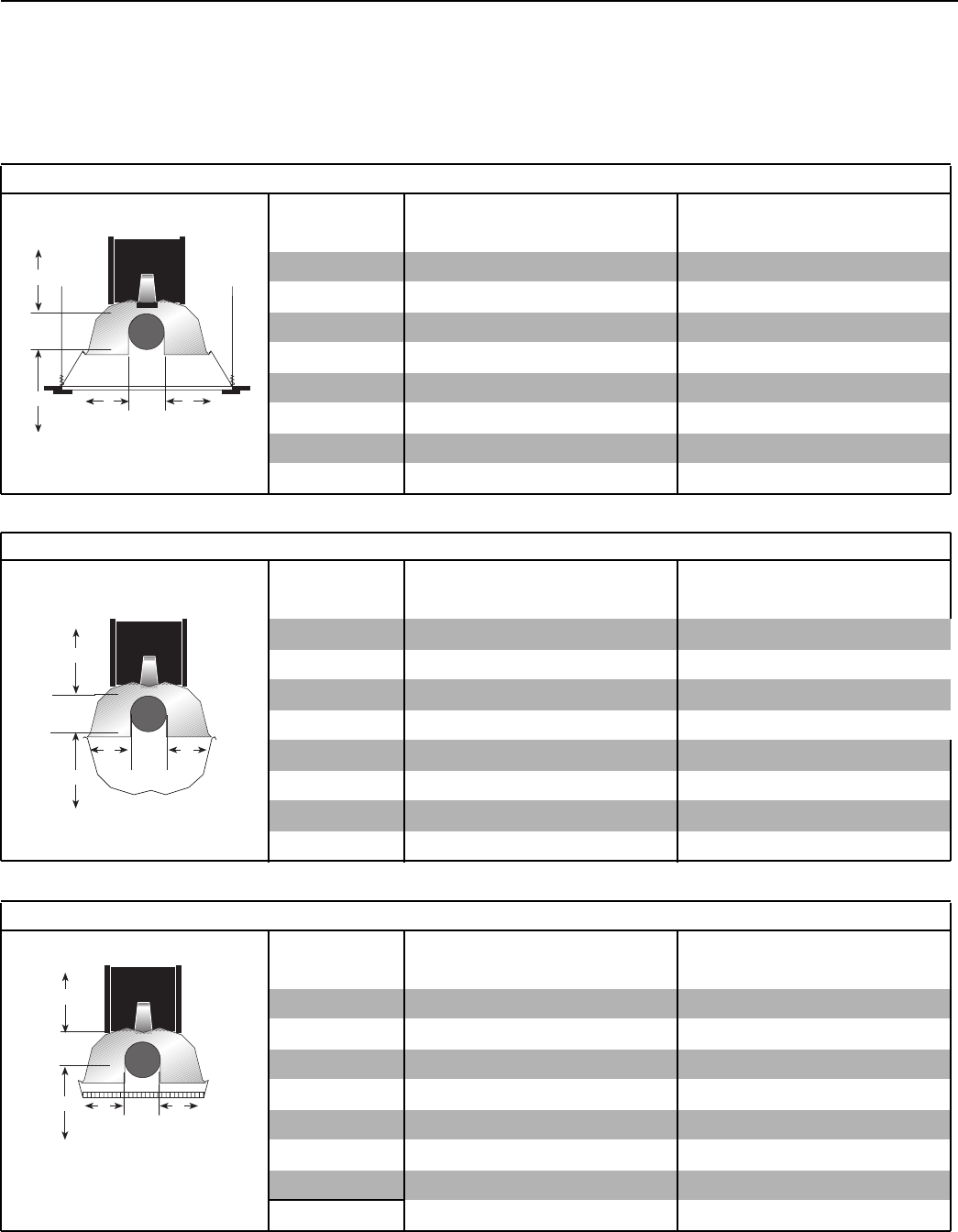
NOTE: 1. All dimensions are from the surfaces of all tubes, couplings, elbows, tees and crosses.
2. Clearances B, C and D can be reduced by 50% after 25' (7.5 m) of tubing downstream from
where the combustion chamber and the tube connect.
3. “-” indicates an unapproved application. Roberts-Gordon prohibits the installation of this heater
for all unapproved applications.
2-Foot Deco Grille
(inches) (centimeters)
Model ABCDABCD
CRV-B-2 4 12 48 12 11 31 122 31
CRV-B-4 4 12 48 12 11 31 122 31
CRV-B-6 4 12 48 12 11 31 122 31
CRV-B-8 4 12 48 12 11 31 122 31
CRV-B-9 4 18 56 18 11 46 143 46
CRV-B-10 4 18 56 18 11 46 143 46
CRV-B-12 4 18 56 18 11 46 143 46
CRV-B-12A 4 18 56 18 11 46 143 46
A
B
C
D
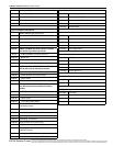
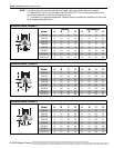
Barrier Shield
(inches) (centimeters)
Model ABCDABCD
CRV-B-2 4 12 12 12 11 31 31 31
CRV-B-4 4 12 12 12 11 31 31 31
CRV-B-6 4 12 12 12 11 31 31 31
CRV-B-8 4 12 12 12 11 31 31 31
CRV-B-9 - - - - - - - -
CRV-B-10--------
CRV-B-12 - - - - - - - -
CRV-B-12A--------
C
A
B
D
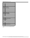
1-Foot Deco Grille
(inches) (centimeters)
Model ABCDABCD
CRV-B-2 4 12 48 12 11 31 122 31
CRV-B-4 4 12 48 12 11 31 122 31
CRV-B-6 4 12 48 12 11 31 122 31
CRV-B-8 4 12 48 12 11 31 122 31
CRV-B-9 4 18 56 18 11 46 143 46
CRV-B-10 4 18 56 18 11 46 143 46
CRV-B-12 4 18 56 18 11 46 143 46
CRV-B-12A 4 18 56 18 11 46 143 46
A
B
C
D