


ROBERTS GORDON
®
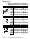
CRV-SERIES SUBMITTAL SHEET
© 2004 Roberts-Gordon
BE FORE INSTAL LATION AND OPERATION OF HEATING EQUIPMENT, READ AND UNDERSTAND T HE INSTALLATION, O PERATION AND SE RVICE MANUAL.
APPLICAT IONS, ENGINEERING AND DETAILED GUIDANCE ON SYSTEMS DESIGN, INSTALLATION AND PRODUCT PERFORMANCE IS AVAILABLE UPO N REQUEST. ROBERTS GORDON
®
PRODUCTS ARE TO BE
INSTALLED ONLY I N ACCORDANCE WITH L OCAL LAWS, CODES AND REGULATIONS, AND ONLY BY A CONTRACTO R QUALIFIED IN THE INSTALLAT ION AND SE RVICE OF GAS-FIRED HEATING EQUIPMEN T.
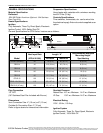
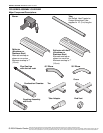
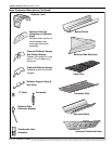
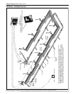
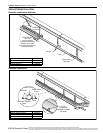
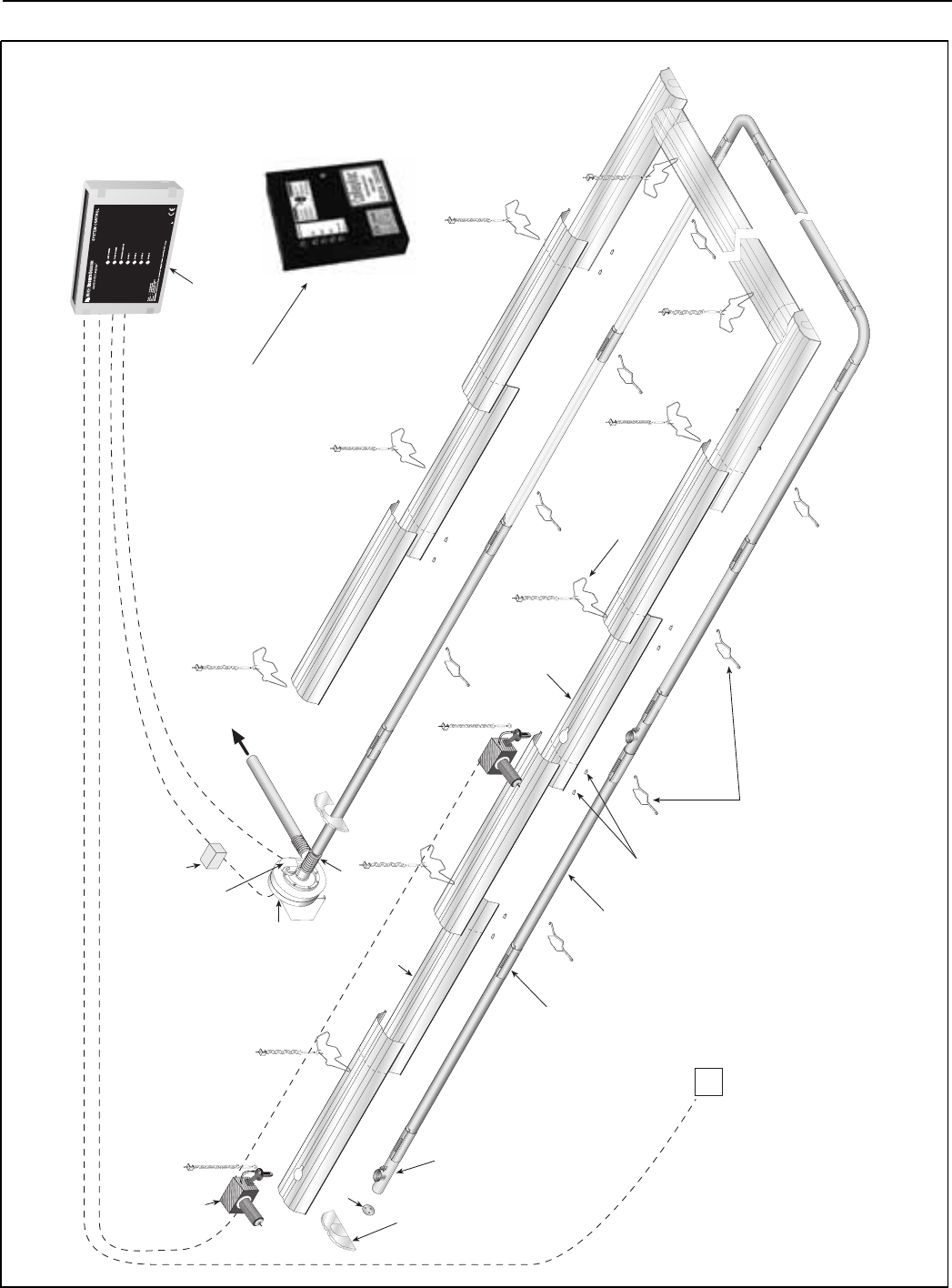
CRV-Series Assembly Overview
End
Vent
Combustion
Chamber
Tube &
Reflector
Hanger
Burner
Reflector
Tube
Coupling
Reflector
End Cap
Reflector
Support
Flexible
Boot
Reflector
with Hole
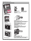
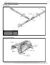
Pump
Exhaust
to Outside
Pressure Switch
S
Zone 1 Sensor or Thermostat**
Relay*
System Control
ROBERTS GORDON
®
BZC Controller
or ROBERTS GORDON
®
ULTRAVAC
Controller
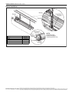
U-Clips
* May not be needed with certain pumps and controllers. Refer to wiring diagram in the
appropriate controller Installation, Operation and Service Manual for details.
**ROBERTS GORDON
®
BZC Controllers require zone sensors. System Control requires
thermostats. ROBERTS GORDON
®
ULTRAVAC
®
requires zone sensors and additional
control equipment. See the appropriate controller installation manual for details.