


ROBERTS GORDON
®
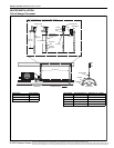
CRV-SERIES SUBMITTAL SHEET
© 2004 Roberts-Gordon
BEFORE IN STALLATION AND OPER ATION OF HEATING EQUIPMENT, READ AND U NDERSTAND THE INSTALLATION, OPERATION AND SERVICE MANUAL.
APPLICATION S, ENGINEERING AND DETAI LED GUID ANCE ON SYSTEMS DESIGN, INSTALLATION AND PRODUCT PE RFORMANCE IS AVAILABLE UPON REQUEST. ROBERTS GORDON
®
PRODUCTS ARE TO BE
INSTALLED ONLY IN ACCORDANCE WITH LOCAL LAWS, CODES AND REGULATIONS, AND ONLY BY A CONTRACTOR QUALIFIED IN THE I NSTALLATION AND SERVICE OF GAS-FIRED HEATING EQUIPMENT.
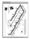
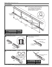
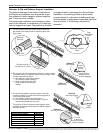
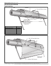
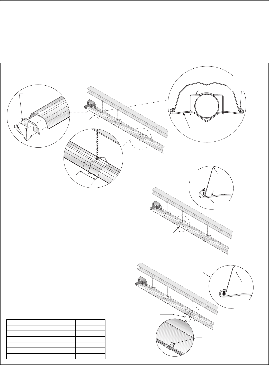
Reflector, U-Clip and Reflector Support Installation
The pictorial drawings of the heater construction in
this Section are schematic only and provide a gen-
eral guideline of where hangers, reflector supports
and U-clips are to be installed.
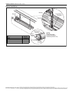
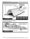
To ensure proper expansion and contraction move-
ment of the reflectors, a combination of U-clips and
reflector supports are used. The positioning of reflec-
tor supports and U-clips depend on the individual
installation. Use either pop rivets or sheet metal
screws instead of u-clips when installing end caps
and joint pieces in areas where impact and high wind
may be a factor. The following rules must be
observed.
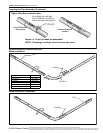
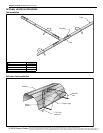
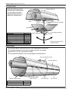
2. The overlap at the first and second reflector is a slip overlap.
Thereafter, every third reflector joint is a slip overlap. A slip
overlap is achieved by either:
a.) both reflectors lay inside a hanger.
(no reflector support needed).
b.) using a reflector support with
loose screws at the reflector
overlap.
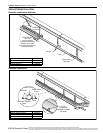
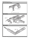
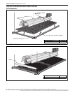
3. The remaining reflector overlaps require a non-slip
overlap connection. To affix the reflectors together in
a non-slip overlap either:
a.) use reflector support and tight screws.
b.) if both reflectors lay inside a hanger, u-clips or
sheet metal screws may be used.
This section of three reflectors joined together must
be affixed to the tube with at least one reflector support
with tight screws.
Reflector
End Cap
U-Clips
Wire Form
Reflector Support
Strap
Tight
Sheet Metal
Screw
1. The first reflector after the burner must be affixed in
the middle of the reflector with a reflector support and
tight screws.
6"
(16 cm)
Overlap must be a
minimum of 6" (16 cm)
First Reflector
Loose screws
loosened 1/16"
to allow slippage.
Option A
Slip Overlap
Reflector
Support
Option B
Slip Overlap
Reflector
Tight
screws
Option B
Non-Slip Overlap
U-Clip
(2 clips per
non-slip overlap
inside a hanger)
Reflector
Option A
Non-Slip Overlap
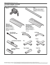
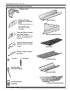
Description Part Number
Reflector Support Package 03050010
Wire Form 91908004
Reflector Support Strap 03050000
Screw #8 x 3/4 94320812
U-Clip Package 91107720
Reflector End Cap 027508XX