


31
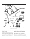
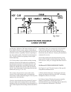
3) Tank and Line Thermometers: Used to determine
proper system operation. Line thermometers will
show an approximate 5 - 12° temperature dif ference
between the collector supply and return lines on sunny
days. In a single tank system the tank thermometer
will read the temperature of the water after the mixing
valve feeding your xtures. In two tank systems
the thermometer will read the nished solar tank
temperature. (Provided)
4) Check Valve: This valve is installed to stop or
minimize convective evening heat loss in the system.
The heat in the solar storage tank will rise through
the collector loop piping in the evening into the
much cooler solar collector and dissipate heat unless
prevented from doing so by a check valve. Check
valves are also sometimes referred to as one way
valves. (Provided)
5) Isolation Ball Valve: Used in conjunction with
component No. 10 to isolate the solar collector loop
from the solar storage tank. (Not Provided)
6) Pressure Relief Valve: Will release glycol loop
HTF at 150 PSI. If this valve opens and HTF uid is
expelled contact your contractor immediately. This
valve also can be opened to drain the HTF from the
charged glycol loop for replacement. (Provided)
7) Pressure Gauge: Indicates the pressure in the
charged glycol collector loop. (Provided)
8) Expansion Tank: Pre-charged with air to allow for
the expansion and contraction of the glycol HTF as it
heats and cools. (Not Provided)
9) Charge Valve: Used to charge the collector loop
with glycol and also to eliminate air from the system.
(Not Provided)
10) Isolation Ball Valve: Used in conjunction with
component No. 5 to isolate the solar collector loop
from the solar storage tank. Also used with the charge
valves to ll and pressurize the collector glycol loop
(Nos. 9 and 11). (Not Provided)
11) Drain/Purge Valve: Used to charge the collector
loop with glycol, purge air from the loop and drain the
heat exchange uid. (Not Provided)
12) Isolation Ball Valve: When closed in conjunction
with No. 14 will isolate the circulation pump for
repair or replacement. (Not Provided)
13) Circulating Pump: Circulates the HTF through the
collector loop. (Provided)
14) Isolation Ball Valve: When closed in conjunction
with No. 12 will isolate the circulation pump for
repair or replacement. (Not Provided)
15) Flush Valve: Used to drain the solar storage tank
and to ush sediment from the tank on an annual
basis. (Not Provided)
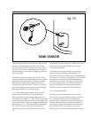
16) Tank Sensor: Wired to your controller. Works
in conjunction with the collector sensor to turn your
circulating pump on and off at preset temperature
differentials. (Provided)
17) Cold Water Dip Tube: Forces incoming city
cold water to the bottom of the solar storage tank to
prevent mixing with the warm water at the top of the
tank. (Provided)
18) Differential Thermostat: Known as the controller.
Automatically turns the circulating pump on and off
when there is sufcient heat to be gained from the
solar operation. The controller also may be set to limit
high temperature build up in the solar storage tank.
(Provided)
19) Heat Exchanger: Transfers heat from the solar
collector loop to the potable water in the solar storage
tank. (Provided)
20) Anode Rod: The "sacricial" anode rod is
installed in your solar storage tank to prevent
corrosion to the tank lining by neutralizing aggressive
water action. Anode rods have a nite life and
require periodic replacement depending on annual
tank temperatures and water quality. Determine
a replacement schedule with your installation
contractor. (Provided)
21) Heating Element & Tank Thermostat: The solar
storage tank is equipped with an auxiliary 4500 watt,
230 volt electrical heating element. The thermostat
controls the temperature setting of the auxiliary
heating element. (Provided)