


30
see that they calibrate to 10K ohm resistance at 77°F.
If you nd a defective sensor replace it immediately.
Note that in a two tank system nighttime heat loss will
be harder to detect, especially if you are operating in
the solar preheat mode. Check the line thermometers
(No. 3) in the collector loop piping to detect night
thermosiphoning.
9.10 If the weather is poor and the auxiliary heating
element will not re, the bright red reset button on
the thermostat may have to be depressed to be reset.
Single tank systems have one heating element and
thermostat. Double tank systems with conventional
electric water heaters have two heating elements and
thermostats (see g 17, No. 29).
Never remove the protective access plate on the
exterior of the solar storage tank or conventional
water heater without disconnecting the 230 volt power
supply at the circuit breaker.
After the circuit breaker has been turned off, remove
the access plate on the storage tank or water heater
and depress the red reset button on the thermostat. If it
clicks when depressed the heating element should re
immediately when you reconnect the circuit breaker.
It the reset button does not click and you do not
have hot water after one hour, the heating element or
thermostat may be defective. Contact your installation
contractor for service.
In two tank systems the conventional electric water
heater will be wired for electrical back-up. The solar
tank will serve solely as a storage tank and will not be
wired.
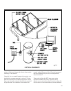
10) Rheem SYSTEM COMPONENT PARTS
See Figures 16 and 17 for the location of the specic
components numbered below.
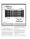
1) Rheem Solar Collector(s): Absorbs the sun's heat
energy and transfers this heat to the HTF circulating
through the collector. (Provided)
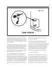
2) Collector Sensor: Wired to the system controller.
Works in conjunction with the tank sensor to
automatically turn your circulating pump on and off at
preset temperature differentials. (Provided)
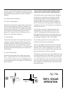
Follow the instructions for single tank systems
above. You also must change the position of the
three way ball valves above both the solar stor-
age tank and the back-up water heater (Nos. 24
and 26). Valve handle No. 24 must be in the hor-
izontal position. Valve handle No. 26 must be in
the vertical position. See Figure 19a, 100% Solar
Operation.
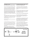
6.5 Solar Preheat
Follow the instructions for the single tank system
for setting the thermostat and the heating ele-
ments for automatic operation. The three way
valve above the solar storage tank (No. 24) must
be in the vertical position. Each valve handle
(Nos. 24, 25 and 26) must be placed in the hori-
zontal position. See Figure 19b, Solar Preheat.
6.6 100% Utility Power
Follow the instructions for the single tank system
above. All three
ball valves above
the heaters (Nos.
24, 25 and 26)
must have the
valve handles
placed in the hor-
izontal position.
See Figures 19c
100% Utility
Power and 19d.
7) ISOLATING
THE MAJOR
COMPONENTS
AND SYSTEM
SHUT DOWN PROCEDURES
Your SolaRay solar water heating system is
designed so that the key components can be eas-
ily isolated for emergency repairs or routine
maintenance. By shutting a single valve you can
isolate the entire system from the pressurized
cold water supply line (No. 23). In the case of a
storage tank or fitting leak immediately shut this
valve and call your installation contractor for
service.
The collector loop can be isolated from the solar
storage tank by closing isolation ball valves Nos.
5 and 10. If the pressure in this loop drops or you
find a glycol leak shut these valves and contact
your installation contractor. Turn the circulating
pump off by setting the controller to the “off”
position.
In two tank systems the solar storage tank can be
isolated from the back-up water heater.
Set the valve handle on the three way ball valve
(No. 24) to the horizontal position and close the
isolation ball valve (No. 25). By closing these two
valves the tank can be serviced or replaced. The
operation of the back-up water heater will not be
effected.
The back-up water heater in two tank systems
also can be isolated from the rest of the system.
Close the cold water supply line ball valve (No.
23) and set the three way valve handle above the
conventional water heater (No. 26) to the vertical
position. Set the two way ball valve handle (No.
30) directly above the heater to the horizontal
position.
8) SUMMER
VACATION REC-
O M M E N D A -
TIONS AND
PROCEDURES
Solar water heat-
ing systems can
build up very high
te mpe rat ures
when there is no
daily draw on the
system. If a short
summer vacation
is planned the
best way to dissi-
P.15
fig.19b
fig.19c
fig.19d
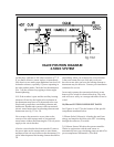
VALVE POSITION DIAGRAM
2-TANK SYSTEM
SOLAR
PREHEAT
100% UTILITY
POWER