


24
Open the upper charge faucet and allow the pressure
from the expansion tank to push the water in the
glycol loop back to prime the pressure pump. When
the hose in the bucket containing the glycol mixture
stops bubbling you may begin charging the collector
loop with glycol.
With both charge faucets now open, run the Flojet
pressure pump until the pinkish glycol mixture begins
owing into the empty bucket. Quickly switch the
hose from the empty/return bucket to the bucket
containing the glycol mixture. Continue to circulate
the uid using the pressure pump until the bubbling
has stopped and the air has been purged.
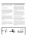
4.11.5 After charging the collector loop, shut the
lower charge faucet and let the pressure pump
drive up the loop pressure to the appropriate level
(Generally in the range of 25 PSI). To more accurately
calculate the proper pressure measure the height of the
solar collector above the solar storage tank and divide
this number by 2.31. Then add 20 PSI to this number.
As a word of caution, the pressure in the glycol
loop should not exceed 45 PSI when the system is
operational on a good sunny day. Contact your solar
contractor if the charged collector loop pressure
exceeds this threshold.
Your Rheem solar water heating system must be
charged and the uid quality maintained by an
experienced contractor. If the system is drained during
the winter, or you notice a signicant drop in collector
loop pressure, contact your installation contractor
immediately for service. The glycol HTF provides
the freeze protection for your system and must be
properly maintained. An experienced contractor
should periodically check the HTF uid quality.
4.11.6 Dowfrost HD HTF
To ensure maximum effectiveness for corrosion
protection, the glycol inhibitor package is designed
for a minimum 25-30 percent concentration of
glycol in water. Table 4 shows the concentrations of
Dowfrost HD required to provide freeze and burst
protection at various temperatures. Use the mixture
most appropriate for your climate. Do not use a
higher glycol to water concentration than necessary,
P.10
manner even a small drip or leak may cause seri-
ous damage to the tank’s electrical components
or, in extreme cases, may cause the tank to leak
from the outside in.
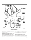
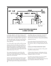
Tank plumbing is required to provide for the iso-
lation of the solar storage tank from the city cold
water supply line by means of an isolating ball
valve (No. 23).
Line thermometers shall be installed in the col-
lector supply and return lines to allow for a sim-
ple diagnostic check of proper system operation.
On a sunny day the hot water return line should
be approximately 5 – 12° warmer than the water
in the collector supply line. Compare the tem-
perature readings in the two line thermometers
(No. 3).
In a single tank system install a third thermome-
ter (No. 3) directly after the mixing valve above
the solar storage tank. In a two tank system you
may install the third thermometer either directly
above the hot outlet on the solar storage tank or
after the mixing valve on the back-up water
heater.
The circulation pump shall be the Grundfos
model UPS15-42F, 115 volt, or equal. The pump
shall be prewired with a 6’ line cord so that it can
be plugged directly into the 115 volt receptacle
on the side of the differential control. Two way
ball valves must be installed on either side of the
circulating pump (Nos.12 and 14) so that the
pump can be isolated from the collector loop.
Repairs or routine system maintenance can be
completed without introducing air into the sys-
tem or draining the HTF.
The expansion tank shall have a minimum 150
PSIG working pressure and have a total volume
of not less than 4.4 gallons. The standard facto-
ry charge should be 40 PSIG. The expansion tank
shall be Rheem/Ruud Therm-X-Guard Model RRT-
12 or equal (No. 8).
A high quality thermostatic mixing valve is a
required component in all OG-300 certified sys-
tems and should be plumbed in line with brass
union connections for ease of future repair or
replacment (No. 32). The specified mixing valve
shall be the Heatguard model HGBASE or equal
and shall have an operating range between 95°F
and 140°F. The mixing valve shall be set to 120°F.
The temperatures generated by your SolaRay sys-
tem will vary throughout the year. In the
Northern Hemisphere the water temperature will
be hottest in the spring and summer months
while cooler temperatures are to be expect from
November through March. On sunny days sys-
tem temperatures may range between 110ºF to
180ºF depending upon the season and hot water
demand. The mixing valve described above
blends the hot and cold water supplies to deliver
hot water to your fixtures at a safe, controlled
temperature.
WARNING: SCALDING CAN OCCUR WITHIN
FIVE SECONDS WHEN WATER TEMPERA-
TURES APPROACH 140ºF. THE MIXING VALVE
SHOULD BE ADJUSTED BY YOUR CONTRAC-
TOR TO PROVIDE WATER TO YOUR FIXTURES
AT NO MORE THAN 120ºF.
The 3/4" cold water supply line to the solar stor-
age tank must be insulated with minimum 7/8"
X 1/2" pipe insulation to a minimum distance of
5' behind the storage tank, or to the wall if clos-
er than 5'.
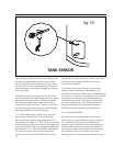
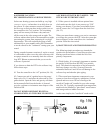
4.9 Tank Sensor Placement
Figure 18 details the proper placement of the
solar storage tank sensor. Make sure the sensor
is secured to the threaded stud on the storage
tank with a 10-24 stainless steel nut.
Thoroughly weatherize the wire connections in
accordance with the roof sensor detail above.
Replace the fiberglass insulation batting and
close the access cover.
4.10 Tank Insulation
SunEarth requires that the solar storage tank
must have a minimum insulation value of R-20.
fig.18
TANK SENSOR