


19
supplies to deliver hot water to your xtures at a safe,
controlled temperature.
!
WARNING: SCALDING CAN OCCUR
WITHIN FIVE SECONDS WHEN WATER
TEMPERATURES APPROACH 140ºF. THE
MIXING VALVE SHOULD BE ADJUSTED BY
YOUR CONTRACTOR TO PROVIDE WATER
TO YOUR FIXTURES AT NO MORE THAN
120ºF.
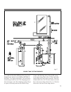
The 3/4" cold water supply line to the solar storage
tank must be insulated with minimum 7/8" X 1/2"
pipe insulation to a minimum distance of 5' behind the
storage tank, or to the wall if closer than 5'.
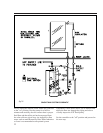
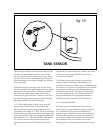
4.9 Tank Sensor Placement
Figure 18 details the proper placement of the solar
storage tank sensor. Make sure the sensor is secured
to the threaded stud on the storage tank with a 10-24
stainless steel nut.
Thoroughly weatherize the wire connections in
accordance with the roof sensor detail above. Replace
the berglass insulation batting and close the access
cover.
A properly licensed contractor must make the 230
volt electrical connection to the water heater or solar
storage tank and the electronic time switch (Optional
No. 33). If your solar contractor is not allowed by
law to make these connections consult a licensed
electrician.
Never activate the circuit breaker controlling the
electrical heating element until the solar storage tank
is completely lled with water. This will prevent “dry
ring” of the heating element. The electrical heating
element will be destroyed almost instantaneously if
not completely submerged in water when activated.
Make sure the water heater circuit breaker is off until
the solar storage tank is completely lled.
collector in the summer months or under stagna-
tion conditions can melt this type of material.
Any above ground exterior pipe insulation is sub-
ject to UV degradation and must be wrapped
with foil tape or painted with two coats of high
quality water-based acrylic resin coating as sup-
plied by the insulation manufacturer. Rubatex
UV Protective Coating or equal is the required
coating material.
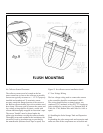
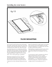
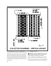
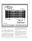
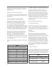
4.5 Collector Plumbing
SunEarth requires the use of all copper and brass
fittings in the collector loop plumbing.
Couplings rather than unions should be used to
join the collectors to avoid leaks and fluid loss.
Use only lead-free solder. Engelhard Silvabrite
100 or equal is required. Use of 50/50 lead sol-
der is expressly prohibited. Use of galvanized
steel, CPVC, PVC, or any other type of plastic
pipe is prohibited.
Piping in new solar installations can be covered
with dirt, grease, solder flux or other impurities
that over time affect the quality of the glycol HTF.
A thorough cleaning is required before charging
the system with glycol. Carefully review the
cleaning procedures in "Charging The System"
outlined below.
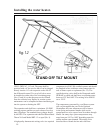
All vertical piping between the storage tank and
the collector shall be supported at each story or
at maximum intervals of ten feet (10'). Copper
plumbers tape or tube strap is required. The pipe
insulation may not be compressed or crimped by
the strapping material.
The installation of all horizontal and vertical pip-
ing may not reduce the performance or rating of
any structural member or fire rated assembly.
Adhere to all applicable local codes and ordi-
nances.
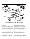
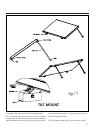
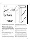
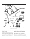
4.6 Collector Sensor Placement
The collector sensor must be located on the hot
water return line as close to the collector as pos-
sible. Sensors are typically accurate to +/- 1/2°F
if properly installed and weatherized. To maxi-
mize sensor accuracy, attach the flanged portion
of the sensor to the SunEarth collector header
pipe with a stainless steel hose clamp. Wire nuts
used to connect the sensor and low voltage
wiring shall be all plastic, sealed with silicone and
thoroughly wrapped in electrician’s tape.
P .7
fig.14
fig.15
fig.13
COLLECTOR
SENSOR
COLLECTOR PLUMBING - VERTICAL MOUNT
COLLECTOR PLUMBING - HORIZONTAL MOUNT