


29
consumed so that the tank lining is not. At a certain
point in the process, the anode rod is no longer
completely effective and the corrosive processes
begin to eat away at the tank's glass lining. In time the
solar storage tank, like any other gas or electric water
heater, will begin to leak. The process is not reversible
and the tank must be replaced.
System temperatures and water quality affect the rate
at which the anode rod is consumed. In general, the
higher the average system temperature the faster the
rate of corrosion. By changing the anode rod after the
fth year of system operation, and every three to ve
years thereafter, it is possible to extend the life of the
solar storage tank. Periodic replacement of the anode
rod in your solar storage tank can signicantly extend
the tank life.
9.3 The solar storage tank also should be ushed
annually to minimize sediment build-up on the bottom
of the tank. If you live in an area with high mineral
content in your water, ush the tank on a semi-annual
basis. Disconnect the power to the solar tank at the
circuit breaker or time switch (if present) before
ushing. Turn the controller to the off position.
Open the ush valve on the bottom of the storage
tank (No. 15) and drain a sufcient volume of water
to eliminate the sediment. After the procedure is
complete make sure the tank is completely full of
water before restoring power to the thermostat and
heating element. Turn the controller to the "on"
position.
9.4 If you live in a dusty climate it is a good idea to
wash off the dirt that settles on the collector glass
once a month. Clean glass allows the collector to
maintain a high level of thermal performance.
9.5 Check the exterior pipe insulation annually and
patch or repair any exposed surfaces or degraded
areas. Repaint as necessary.
9.6 In the unusual instance of collector glass
breakage, the glass should be replaced immediately.
This will reduce the likelihood of water accumulating
inside the collector and deteriorating the insulation.
Contact your installation contractor.
9.7 If you detect a glycol or water leak, or the glycol
loop pressure drops unexpectedly, contact your
installation contractor immediately to diagnose the
problem and recharge the system.
9.8 If it’s been a sunny day and you don’t have hot
water, rst make sure that the controller is set in the
automatic position. If the controller is properly set
and the pump has not been running, unplug the line
cord from the controller receptacle and plug the pump
directly into a nearby 115 volt outlet. If the pump does
not run it may need to be replaced. If the pump does
run when plugged directly into the wall outlet, the
problem may be located in the controller or one of the
10k ohm sensors. Contact your installation contractor
for service.
9.9 If you have a full tank of hot water before bed
and the solar storage tank is cold in the morning, the
check valve (No. 4) may not be seating correctly and
should be cleaned or replaced. Also make sure that
the circulating pump is not running after 6:00 p.m.
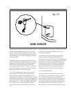
If the pump is running and the control indictor light
"Solar" #1 is on after 6:00 p.m., check both sensors to
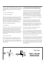
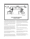
Follow the instructions for single tank systems
above. You also must change the position of the
three way ball valves above both the solar stor-
age tank and the back-up water heater (Nos. 24
and 26). Valve handle No. 24 must be in the hor-
izontal position. Valve handle No. 26 must be in
the vertical position. See Figure 19a, 100% Solar
Operation.
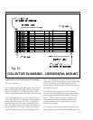
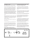
6.5 Solar Preheat
Follow the instructions for the single tank system
for setting the thermostat and the heating ele-
ments for automatic operation. The three way
valve above the solar storage tank (No. 24) must
be in the vertical position. Each valve handle
(Nos. 24, 25 and 26) must be placed in the hori-
zontal position. See Figure 19b, Solar Preheat.
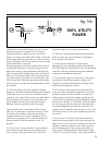
6.6 100% Utility Power
Follow the instructions for the single tank system
above. All three
ball valves above
the heaters (Nos.
24, 25 and 26)
must have the
valve handles
placed in the hor-
izontal position.
See Figures 19c
100% Utility
Power and 19d.
7) ISOLATING
THE MAJOR
COMPONENTS
AND SYSTEM
SHUT DOWN PROCEDURES
Your SolaRay solar water heating system is
designed so that the key components can be eas-
ily isolated for emergency repairs or routine
maintenance. By shutting a single valve you can
isolate the entire system from the pressurized
cold water supply line (No. 23). In the case of a
storage tank or fitting leak immediately shut this
valve and call your installation contractor for
service.
The collector loop can be isolated from the solar
storage tank by closing isolation ball valves Nos.
5 and 10. If the pressure in this loop drops or you
find a glycol leak shut these valves and contact
your installation contractor. Turn the circulating
pump off by setting the controller to the “off”
position.
In two tank systems the solar storage tank can be
isolated from the back-up water heater.
Set the valve handle on the three way ball valve
(No. 24) to the horizontal position and close the
isolation ball valve (No. 25). By closing these two
valves the tank can be serviced or replaced. The
operation of the back-up water heater will not be
effected.
The back-up water heater in two tank systems
also can be isolated from the rest of the system.
Close the cold water supply line ball valve (No.
23) and set the three way valve handle above the
conventional water heater (No. 26) to the vertical
position. Set the two way ball valve handle (No.
30) directly above the heater to the horizontal
position.
8) SUMMER
VACATION REC-
O M M E N D A -
TIONS AND
PROCEDURES
Solar water heat-
ing systems can
build up very high
t em p er at u r es
when there is no
daily draw on the
system. If a short
summer vacation
is planned the
best way to dissi-
P.15
fig.19b
fig.19c
fig.19d
VALVE POSITION DIAGRAM
2-TANK SYSTEM
SOLAR
PREHEAT
100% UTILITY
POWER