


8 Regency U38 ULTIMATE Freestanding Gas Stove
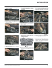
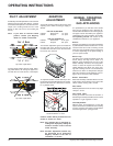
5) The pressure check should be carried out
with the unit burning and the setting should
be within the limits specified on the safety
label.
6) When finished reading manometer, turn off
the gas valve, disconnect the hose and
tighten the screw (clockwise) with a 1/8"
flat screwdriver. Screw should be snug,
but do not over tighten.
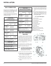
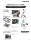
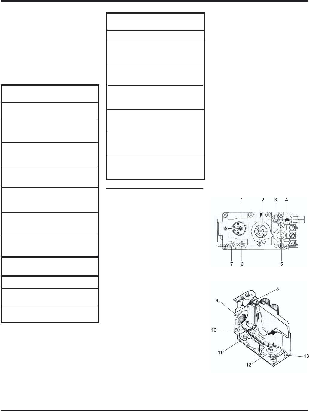
S.I.T. Valve Description
1) Gas cock knob
2) Manual high/low adjustment
3) Pilot Adjustment
4) Thermocouple Connection
5) Main Operator
6) Outlet Pressure Tap
7) Inlet Pressure Tap
8) Pilot Outlet
9) Main Gas Outlet
10)Flange Securing Screw Holes
11)Alternative TC Connection Point
12)Thermoelectric Unit
13)Additional Valve Mounting Hole
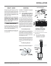
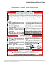
GAS PIPE PRESSURE
TESTING
The appliance must be isolated from the gas
supply piping system by closing its individual
manual shut-off valve during any pressure
testing of the gas supply piping system at test
pressures equal to or less than 1/2 psig. (3.45
kPa). Disconnect piping from valve at pres-
sures over 1/2 psig (14" w.c.).
The manifold pressure is controlled by a regu-
lator built into the gas control, and should be
checked at the pressure test point.
Note: To properly check gas pressure,
both inlet and manifold pressures
should be checked using the valve
pressure ports on the valve.
1) Make sure the valve is in the "OFF" position.
2) Loosen the "IN" (# 7) and/or "OUT" (# 6)
pressure tap(s), turning counterclockwise
with a 1/8" wide flat screwdriver.
3) Attach manometer to "IN" and/or "OUT"
pressure tap(s) using a 5/16" ID hose.
4) Light the pilot and turn the valve to "ON"
position.
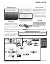
INSTALLATION
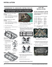
U38-NG: For 0 to 2000 feet altitude
U38-LP: For 0 to 4500 feet alttitude
Burner Inlet Orifice Sizes:
Natural Gas Propane
Burner #31 #50
Max. Input
Natural Gas 40,000 Btu/h
Propane 38,000 Btu/h
Min. Input
Natural Gas 22,000 Btu/h
Propane 20,000 Btu/h
Supply Pressure
Natural Gas min. 5" w.c.
Propane min. 12" w.c.
Manifold Pressure
Natural Gas 3.8" +/- 0.2" w.c.
Propane 11" +/- 0.2" w.c.
Electrical: 120 V. 1.13A 60Hz.
Circulation: Variable speed fan, 125/75 CFM.
Log Set: Ceramic fiber, 7 per set.
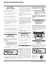
System Data:
HIGH ELEVATION - U38-NG
For 2,000 - 4,500 feet altitude
Burner Inlet Orifice Sizes:
Natural Gas Burner #33
Max. Input Rating 36,000 Btu/h
Min. Input Rating 19,000 Btu/h
System Data
U38 with 40,000 BTU
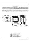
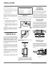
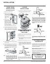
GAS CONNECTION
The gas line can be rigid pipe, or to make
installation easier, use a listed flexible connec-
tor if allowed by local codes. Copper may also
be used if approved by local codes.
The gas connection at the valve is 3/8" NPT. For
minimum and maximum supply pressure see
the System Data Table.
System Data
U38 Converted to 30,000 Btu
For 0 to 4500 feet altitude
Burner Inlet Orifice Sizes:
Natural Gas Propane
Burner #37 #52
Max. Input
Natural Gas 30,000 Btu/h
Propane 30,000 Btu/h
Min. Input
Natural Gas 15,000 Btu/h
Propane 15,000 Btu/h
Supply Pressure
Natural Gas min. 5" w.c.
Propane min. 12" w.c.
Manifold Pressure
Natural Gas 3.8" +/- 0.2" w.c.
Propane 11" +/- 0.2" w.c.
Electrical: 120 V. 1.13A 60Hz.
Circulation: Variable speed fan, 125/75 CFM.
Log Set: Ceramic fiber, 7 per set.