


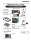
6 Regency U38 ULTIMATE Freestanding Gas Stove
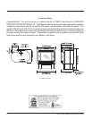
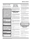
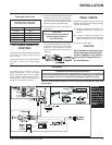
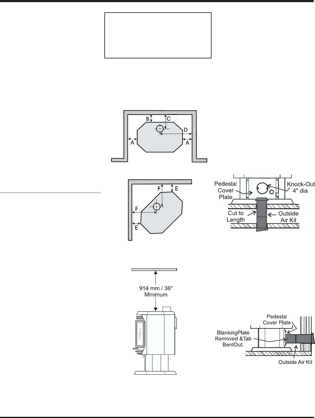
Side View
Rear View
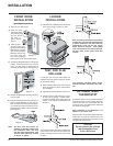
Outside Air Through
Rear of Pedestal
Remove the blanking plate from the rear of the
pedestal cover plate and bend the two tabs out
90 degrees. Pipe fresh air into the pedestal area
by using duct pipe with a mesh grill at the outside
termination. Attach the pipe to the tabs with
screws.
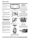
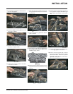
OPTIONAL
OUTSIDE AIR
Outside air for combustion can be brought in
either through the bottom of the pedestal or
through the rear plate of the pedestal.
For both bottom and rear "outside air" the Ped-
estal Cover Plate must be installed. Loosen the
4 screws on the rear of the pedestal and slide
the cover plate over them. Slide the plate to the
left to center it and tighten down the 4 screws.
Outside Air Through
Pedestal Bottom
Once you have properly marked the position of
your unit as outlined in "General Information"
and "Clearances to Combustibles", cut a prop-
erly sized hole though the floor directly under
your pedestal base to the outside. Pipe fresh air
into the pedestal area by using appropriate
metallic duct pipe with a mesh grill at the outside
termination. Do not remove the knockout.
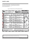
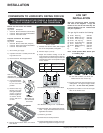
INSTALLATION
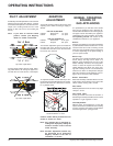
CLEARANCES TO
COMBUSTIBLES
The clearances listed below are MINIMUM dis-
tances. Measure the clearance to both the
appliance and the chimney connector. (The
farthest distance is correct if the two
clearances do not coincide.) For example, if
the appliance is set as indicated in one of the
figures but the connector is too close, move the
stove until the correct clearance to the connec-
tor is obtained.
This unit can be installed on a solid combustible
surface like a wood floor. This unit can also be
installed directly on carpeting or vinyl when the
bottom pedestal cover plate (provided with unit)
is installed.
This appliance may be installed only with the
clearances as shown in the situations pictured.
Do not combine clearances from one type of
installation with another in order to achieve
closer clearances.
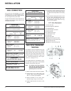
Use the minimum clearances shown in the
diagrams below for installation with "B" vent.
Minimum ceiling height is 36" / 914 mm
from top of unit.
9) Install Louvers, page 12.
10)Test for flue spillage (draft test), page 12.
11)Install optional Remote Control, or Wall Ther-
mostat, pages 12 and 13.
12)Final check, page 13.
Before leaving this unit with the customer, the
installer must ensure that the appliance is firing
correctly and operation fully explained to cus-
tomer.
This includes:
1) Clocking the appliance to ensure the cor-
rect firing rate (rate noted on label) after
burning appliance for 15 minutes.
2) If required, adjusting the primary air to
ensure that the flame does not carbon. First
allow the unit to burn for 15-20 min. to
stabilize.
CAUTION: Any alteration to the product that
causes sooting or carboning or that results in
damage is not the responsibility of the manu-
facturer.
U38-NG & U38-LP Clearances
A Side Wall to Unit 7-1/2" / 190 mm
B Back Wall to Unit 6" / 155 mm
E Side Wall to Unit 2" / 50 mm
If further reduced clearances are needed, ob-
tain requirements for construction of a protect-
ed wall from your local building authorities and
their allowable reductions of the listed clear-
ances.
U38-NG & U38-LP REFERENCE
DIMENSIONS
C Back Wall to Flue Centerline 10-3/4" / 273 mm
D Side Wall to Flue Centerline 20-1/2" / 520 mm
F Side Wall to Flue Centerline 11" / 280 mm