


12 Regency U38 ULTIMATE Freestanding Gas Stove
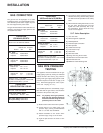
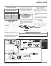
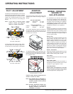
OPTIONAL WALL
THERMOSTAT
A wall thermostat may be installed if desired.
Connect the wires as per the wiring diagrams.
Note that the wires are connected to the "TH"
on the gas valve. Use table below to determine
the maximum wire length:
Note: Preferable if the thermostat is in-
stalled on an interior wall.
Regency offers an optional programmable ther-
mostat but any 250-750 millivolt rated non-
anticipator type thermostat that is CSA, ULC or
UL approved may be used.
CAUTION
Do not connect the millivolt
wall thermostat wires
to the 120V wires.
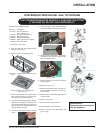
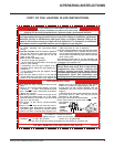
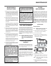
The thermally activated safety switch
must be manually reset before first star-
tup.
Note: If the flue is blocked or has a strong
reverse flow, the thermally actuated safe-
ty switch mounted in the draft hood will
automatically shut off the gas supply
within about 10 minutes. If the heater
turns off because of this during the spill-
age test, check for the cause of the lack
of draft.
TEST FOR FLUE
SPILLAGE
A "spillage" test must be made before the
installed unit is left with the customer. Follow
the procedure below:
1) Start all exhaust fans in the home and any
other gas appliances. Then close all doors
and windows.
2) Light the unit and set controls to maximum.
3) After five minutes, test that there is a "pull"
on the flue by placing a smoke match,
cigarette or similar device which gives off
smoke, on the edge of the draft hood. See
diagrams.
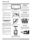
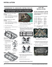
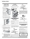
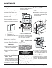
LOUVER
INSTALLATION
1) Attach the top & bottom louvers to the side
stove panel using 2 screws per side.
Diagram 1
FRONT DOOR
INSTALLATION
(packaged separately)
1) Open the two side panels.
2) Slide the door
onto the two hinge
pins making sure
the two pieces
are flush to-
gether. See di-
agram 1.
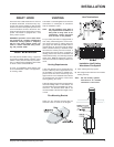
3) Close the door.
The latch plate must
plate slightly so the door closes easier.
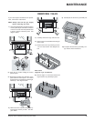
4) The latches should already be at the proper
setting. If they are too hard or too easy to
close, you may want to adjust them by
loosening the latch catch. See diagram 3.
Diagram 2
Diagram 3
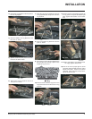
INSTALLATION
5) Remove the blue plastic protective coating
from the glass.
6) Test the seal around the door by placing a
piece of paper between the unit and the
door, close the door and try to pull the paper
out. If it slips out easily, then the door is not
properly sealed. Tighten or loosen the latch.
See diagram 3.
be centered around the
alignment pin. See dia-
gram 2. If the latch plate
interferes with the cor-
ner of the stove you
may want to angle the
Note: The door latch may require ad-
justment as the door gasket mate-
rial compresses after a few fires
and after glass replacement. Turn
the latch catch inward or outward
to loosen or tighten.
The smoke should be drawn into the draft hood.
If the smoke is not drawn into the draft hood,
turn the unit off and check for the cause of lack
of draft.
.