


Regency
®
P36-4 Gas Log Fireplace 21
OPTIONAL
BRICK PANELS
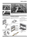
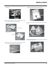
1) Undo the bottom 2 door latches and open
and remove glass door. Remove logs.
Note: The logs must not be in the unit.
2) Insert the back brick panel fi rst by carefully
slipping it between the back wall of the
fi rebox and the rear log bracket.
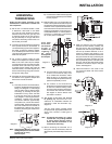
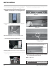
4) Light the pilot and turn the valve to "ON"
position.
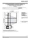
5) The pressure check should be carried out
with the unit burning and the setting should
be within the limits specifi ed on the safety
label.
6) When fi nished reading manometer, turn
off the gas valve, disconnect the hose and
tighten the screw (clockwise) with a 1/8" fl at
screwdriver. Note: Screw should be snug,
but do not over tighten.
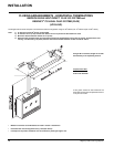
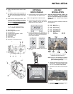
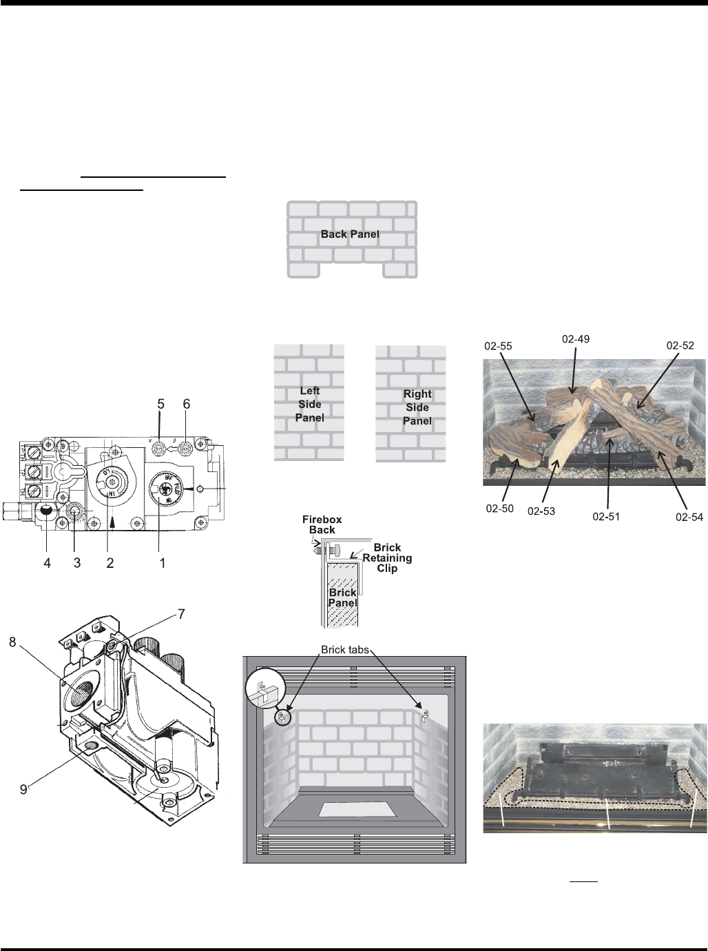
S.I.T. VALVE DESCRIPTION
1) Gas on/off knob
2) Manual high/low adjustment
3) Pilot Adjustment
4) Thermocouple Connection - option
5) Outlet Pressure Tap
6) Inlet Pressure Tap
7) Pilot Outlet
8) Main Gas Outlet
9) Alternative TC Connection Point
3) Put the side panels in next. Slide them in
from the front and push them fl at up against
the wall. Be very careful not to scratch them
on the fi rebox hardware.
4) Install the 2 brick retaining clips, one on
each side.
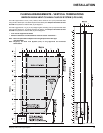
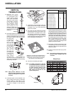
LOG SET
INSTALLATION
Read the instructions below carefully and
refer to the diagrams. If logs are broken
do not use the unit until they are replaced.
Broken logs can interfere with the pilot
operation.
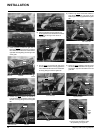
The gas log kit (Part # 512-930) contains the
following pieces:
a) 02-49 Rear Log
b) 02-55 Middle Left Log
c) 02-50 Front Left Log
d) 02-53 Center Left Log
e) 02-51 Front Bottom Log
f) 02-54 Center Right Log
g) 02-52 Middle Right Log
h) Embers 902-156
i) Vermiculite 902-179
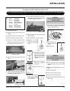
NOTE: If you will be installing the optional
Brick Panels, install the Brick Panels
prior to installing the logs.
1) Carefully remove the logs from the box and
unwrap them. The logs are fragile, handle
with care - do not force into position.
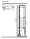
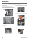
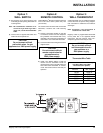
2) Sprinkle the vermiculite around the fi rebox
base.
Vermiculite
Vermiculite
Vermiculite
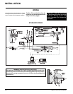
The "02" refer numbers (i.e. 02-49) are
molded into the rear of each log.
3) Place the Log 02-49 on the rear log support
pins with the fl at side to the back.
INSTALLATION