


Regency
®
P36-4 Gas Log Fireplace
20
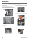
GAS PIPE PRESSURE
TESTING
The appliance must be isolated from the gas
supply piping system by closing its individual
manual shut-off valve during any pressure
testing of the gas supply piping system at
test pressures equal to or less than 1/2 psig.
(3.45 kPa). Disconnect piping from valve at
pressures over 3.45 kPa.
The manifold pressure is controlled by a
regulator built into the gas control, and should
be checked at the pressure test point.
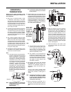
Note: To properly check gas pressure, both
inlet and manifold pressures should
be checked using the valve pressure
ports on the valve.
1) Make sure the valve is in the "OFF"
position.
2) Loosen the "IN" and/or "OUT" pressure
tap(s), turning counterclockwise with a
1/8" wide fl at screwdriver.
3) Attach manometer to "IN" and/or "OUT"
pressure tap(s) using a 5/16" ID hose.
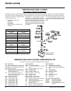
P36-NG System Data
For 0 to 4500 feet altitude
Burner Inlet Orifi ce Sizes: #37( 2.65mm)
Max. Input Rating 33 mj
Min. Input Rating 20 mj
Supply Pressure min.1.25 kPa
Manifold Pressure
(High) 0.9 kPa
Electrical: 240 V A.C. System.
Circulation Fan: variable speed 130 CFM.
Log Set: Ceramic fi bre, 7 per set.
Flue System: Simpson Dura-Vent Direct
Flue System or Regency
®
Direct
Flue System (Flex)
P36-LPG System Data
For 0 to 2000 feet altitude
Burner Inlet Orifi ce Sizes: #52 (1.6 mm)
Max. Input Rating 31 mj
Min. Input Rating 18 mj
For 0 to 4500 feet Altitude:
Supply Pressure min 2.75 kPa
Manifold Pressure
(High) 2.7 kPa
Electrical: 240 V A.C. System.
Circulation Fan: variable speed 130 CFM.
Log Set: Ceramic fi bre, 7 per set.
Flue System: Simpson Dura-Vent Co Axial
Flue System
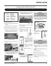
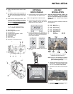
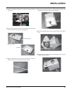
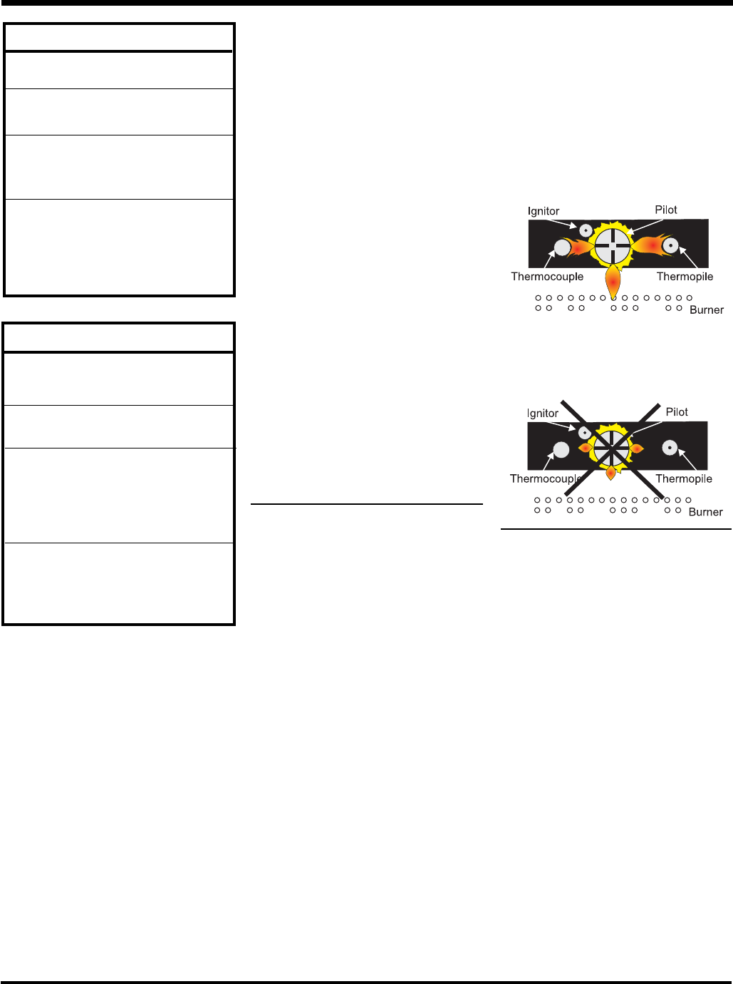
PILOT ADJUSTMENT
Periodically check the pilot fl ames. Correct
fl ame pattern has three strong blue fl ames:
1 fl owing around the thermopile, 1 around
the thermocouple and 1 fl owing across the
burner (it does not have to be touching the
burner).
Note: If you have an incorrect fl ame pattern,
contact your Regency
®
dealer for
further instructions.
Incorrect fl ame pattern will have small,
probably yellow fl ames, not coming into
proper contact with the rear burner or
thermopile or thermocouple.
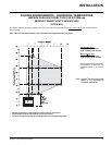
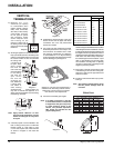
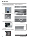
AERATION
ADJUSTMENT
The air shutter can be adjusted by moving the
adjusting wire up or down. The wire is accessed
through the bottom louvre opening. Open the air
shutter for a blue fl ame or close for a yellower
fl ame. The burner aeration is factory set but
may need adjusting due to either the local gas
supply or altitude. This adjustment is performed
by the gas fi tter.
Minimum Air Shutter Opening:
8 mm NG
Full Open LPG
CAUTION: Carbon will be produced if air shutter
is closed too much.
Note: Any damage due to carboning
resulting from improperly setting
the aeration controls is NOT covered
under warranty.
Closed - Tall yellow
Open - Short Blue
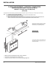
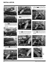
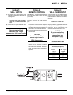
GAS LINE
INSTALLATION
The gas line can be brought through either the
right or the left side of the appliance. The gas
valve is situated on the right hand side of the
unit and the gas inlet is on the right hand side
of the valve.
Note: If the gas line is being installed from
the left side, be sure to leave room to
accommodate servicing of the fan.
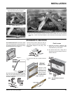
The gas line connection may be made of
rigid pipe, copper pipe or an approved fl ex
connector. (If you are using rigid pipe, ensure
that the valve can be removed for servicing.)
Since some municipalities have additional local
codes it is always best to consult with your local
authorities and the AS5601-2004 or NZS 5261
installation code.
When using copper or fl ex connectors use only
approved fi ttings. Always provide a union so
that gas lines can be easily disconnected for
servicing. Flare nuts for copper lines and fl ex
connectors are usually considered to meet this
requirement.
Important: Always check for gas leaks with a
soap and water solution or gas leak detector.
Do not use open fl ame for leak testing.
INSTALLATION