


20 U37-1 Regency
®
ULTIMATE Rear Vent Direct Vent Freestanding Gas Stove
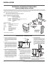
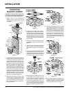
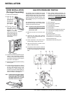
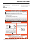
AERATION
ADJUSTMENT
The burner aeration is factory set but may need
adjusting due to either the local gas supply, air
supply or altitude.
Natural Gas: 1/4" open
Propane: 3/8" open
The aeration adjustment gears are located on
the right side of the burner box and can be ac-
cessed from the side or from the front when the
louvers are removed.
To adjust the aeration: use the allen key to turn
the turning gear which will adjust the air shutter.
Open the air shutter for a blue fl ame or close it
for a yellower fl ame. The factory setting should
be suffi cient for most installations.
Clockwise to open,
counter-clockwise to close.
Caution: Carbon will be produced if the air
shutter is closed too much.
Note: Any damage due to carboning result-
ing from improperly setting the aera-
tion controls is NOT covered under
warranty.
Note: Aeration Adjustment should only be
performed by an authorized Regency
®
Installer at the time of installation or
service.
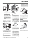
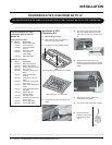
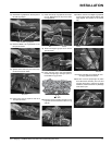
LOG SET
INSTALLATION
Read the instructions below carefully and
refer to the diagrams. If logs are broken
do not use the unit until they are replaced.
Broken logs can interfere with the pilot
operation.
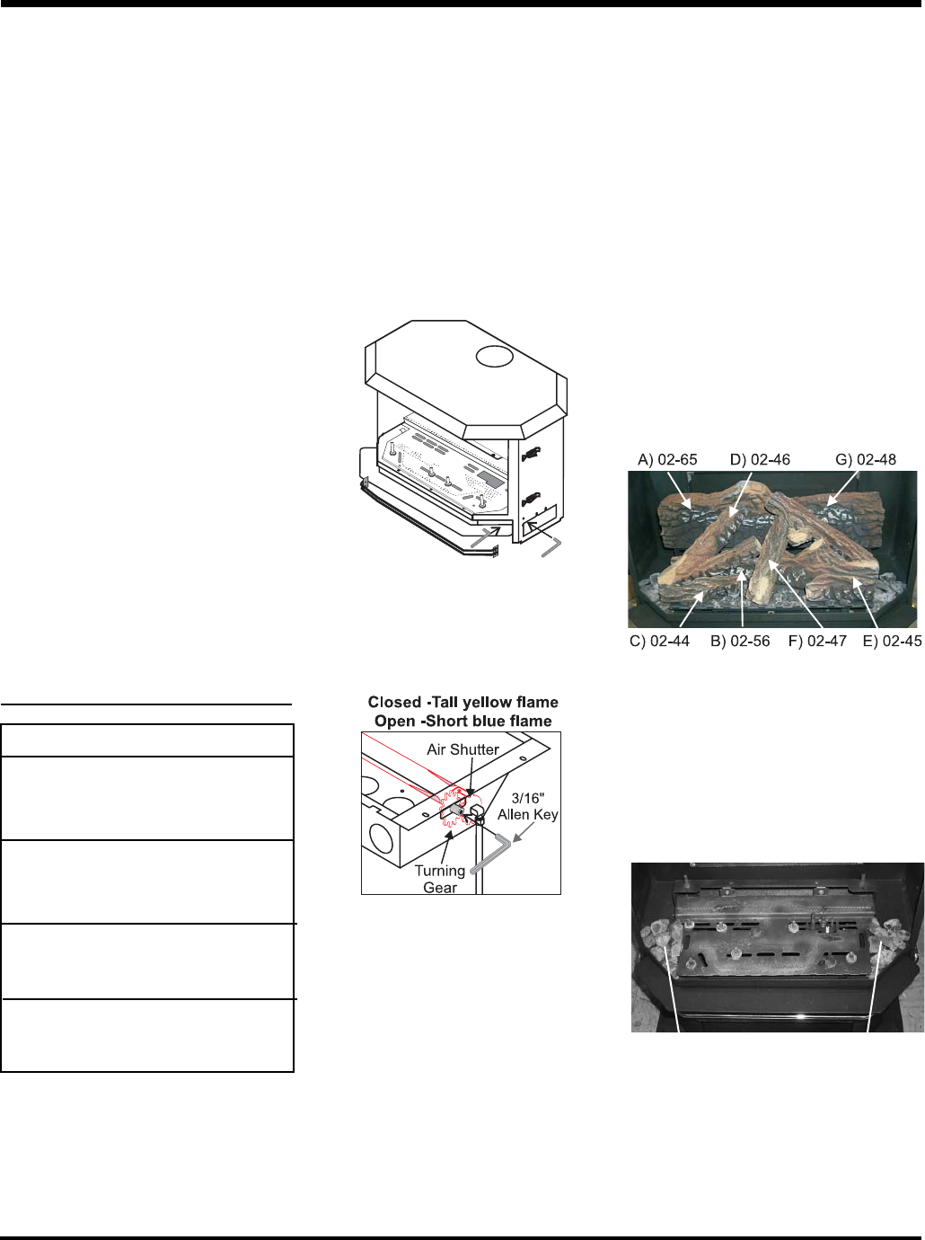
The gas log kit contains the following:
a) 02-65 Rear Log
b) 02-56 Middle Left Log
c) 02-44 Front Left Log
d) 02-46 Left Top Log
e) 02-45 Front Right Log
f) 02-47 Center Log
g) 02-48 Middle Right Log
h) Embers 902-151
i) Lava 902-154
Embers. Embers
The "02" refer numbers (i.e. 02-65) are
molded into the rear of each log.
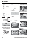
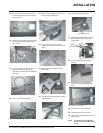
1) Carefully remove the logs from the box and
unwrap them. The logs are fragile, handle
with care - do not force into position.
2) Sprinkle the embers on the left and right
sides of the fi rebox base.
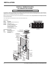
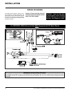
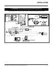
GAS CONNECTION
The gas connection is a 3/8" NPT 90
o
elbow.
The gas line can be rigid pipe or to make in-
stallation easier, use a listed fl exible connector
and/or copper tubing if allowed by local codes.
Since some municipalities have additional local
codes it is always best to consult with your local
authorities and the CAN/CGA B149 installation
codes. For USA installations follow local codes
and/or the current National Fuel Gas Code,
ANSI Z223.1.
When using copper or fl ex connectors use only
approved fi ttings. Always provide a union so
that gas lines can be easily disconnected for
burner and/or valve servicing. Flare nuts for
copper lines and fl ex connectors are usually
considered to meet this requirement.
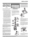
Important: Always check for gas leaks with a
soap and water solution or gas leak detector.
Do not use open fl ame for leak testing.
Note: Prior to any pressure testing of
the gas supply piping system
that exceeds test pressures of
1/2 psig, this appliance must be
disconnected from the piping
system. If test pressures equal to
or less than 1/2 psig are used then
this appliance must be isolated
from the piping system by clos-
ing its individual manual shut-off
valve during the testing.
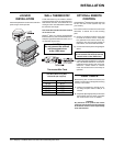
HIGH ELEVATION
This unit is approved in Canada for altitude 0 ft.
to 4500 ft. (CAN/CGA-2.17-M91). For Natural
Gas installations above 4500 ft. follow current
CAN/CGA-B149.1.
System Data - U37
For 0 to 4500 feet altitude
Burner Inlet Orifi ce Sizes:
Natural Gas Propane
Burner #37 #52
Max. Input Rating 30,000 Btu/h
Min. Input Rating 15,000 Btu/h
Supply Pressure
Natural Gas min. 5.0" w.c.
Propane min. 12.0" w.c.
Manifold Pressure
Natural Gas 3.8" +/- 0.2" w.c.
Propane 11" +/- 0.2" w.c.
INSTALLATION