


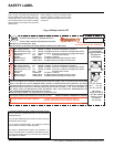
12 U37-1 Regency
®
ULTIMATE Rear Vent Direct Vent Freestanding Gas Stove
INSTALLATION
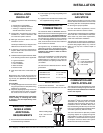
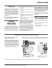
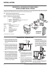
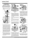
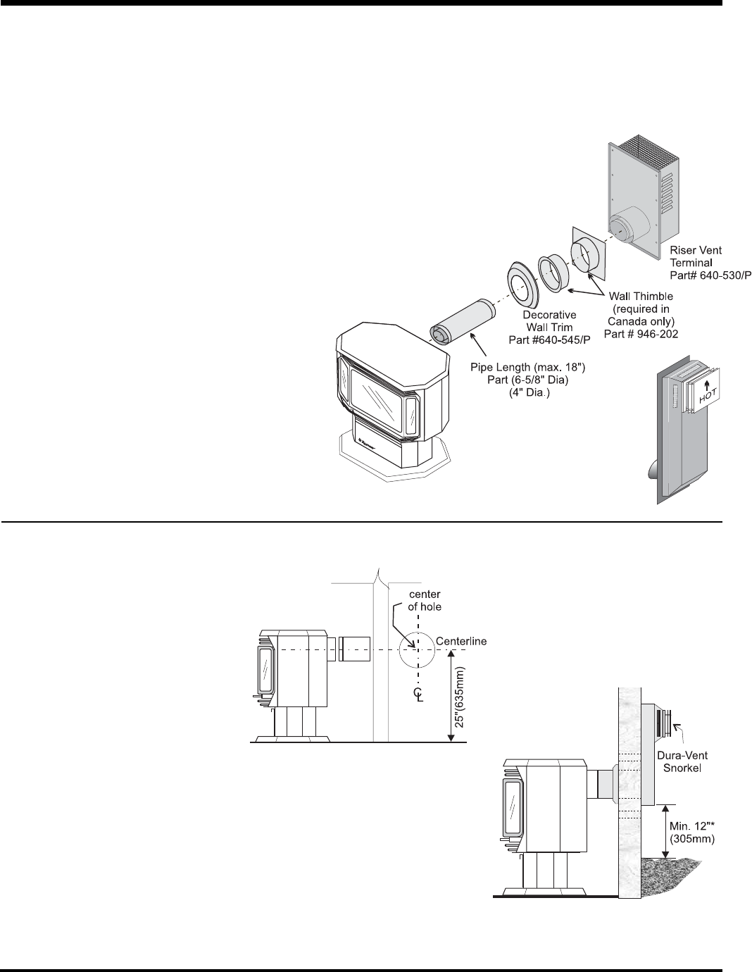
Diagram 2a
HORIZONTAL TERMINATIONS
Diagram 1
*Dia 2a & 2b: As specifi ed in CGA B149 Instal-
lation Code. Local codes or regulations may
require different clearances.
RESIDENTIAL AND MANUFACTURED HOMES /
MOBILE HOMES INSTALLATIONS
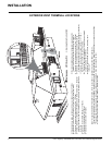
You will require the following components with your new Regency
®
Rear Vent Direct Vent Freestanding Gas Stove. Please review your product to
make sure you have everything you need. In the event that you are missing any part, contact your dealer. Decorative brass or chrome trim kits are
available from Simpson Dura-Vent for their wall thimbles, as well as a square wall thimble cover.
Note: These are the minimum pieces required.
Other parts may be required for your particular installation.
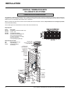
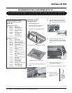
Minimum components for a Horizontal Installation:
640-944 Horizontal Termination Kit which includes:
1 6-5/8" Dia. x 18" Black Pipe
1 4" Dia. x 18" Aluminum Vent
1 640-530/P Riser Vent Terminal
1 946-202 Wall Penetration Heat Shield (Wall Thimble) (2 pcs)
1 640-545/P Decorative Wall Trim (Black)
1 948-128 Tube Mill-Pac
Screws
Optional Components:
946-204 45
o
Elbow - 6-5/8" Black pipe and 4"
Aluminum Vent
946-205 Vinyl Siding Shield for Riser Vent
Terminal
946-208/P Vent Guard
940 Square Wall Thimble Cover*
981 Snorkel Termination (36")*
982 Snorkel Termination (14")*
942 Wall Penetration
Heat Shield*
* Simpson Dura-Vent components
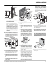
Alternate Snorkel
Termination Cap
Part # 982 (14")
Part # 981 (36")
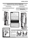
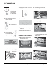
1) Set the unit in its desired location. Check to
determine if wall studs are in the way when
the venting system is attached. If this is the
case, you may want to adjust the location
of the unit.
2) Assemble the desired combination of pipe
and elbow to the appliance adapter with
pipe seams oriented down. Offset the pipe
seams as double seams in one place will
cause the outer pipe to take an oval shape.
Kit comes complete with 18" of straight vent
- 6-5/8" dia. black outer pipe and 4" dia. inner
vent.
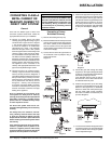
3) With the pipe attached to the stove, slide the
stove into its correct location, and mark the
wall for a 9-1/2" (inside dimensions) round
hole. The center of the round hole should line
up with the centerline of the horizontal pipe,
as shown in diagram 1. Cut and frame the
9-1/2 round hole in the exterior wall where
the vent will be terminated. If the wall being
penetrated is constructed of non-combusti-
ble material, i.e. masonry block or concrete,
a 7" diameter hole is acceptable.
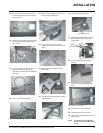
Note:
a) The horizontal run of vent should have
a 1/4 inch rise for every 1 foot of run
towards the termination. Never allow the
vent to run downward. This could cause
high temperatures and may present the
possibility of a fi re.
b) The location of the horizontal vent ter-
mination on an exterior wall must meet
all local and national building codes,
and must not be blocked or obstructed.
For External Vent Terminal Locations,
see diagram in "Exterior Vent Terminal
Locations" section.
c) Snorkel Terminations:
For installations requiring a vertical rise
on the exterior of the building, 14-inch
and 36-inch tall Snorkel Terminations
as shown in Dia. 2 are available, as
well as the standard Riser Vent. Follow
the same installation procedures as
used for standard Horizontal Termina-
tion. NEVER install the snorkel upside
down.