


U37-1 Regency
®
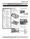
ULTIMATE Rear Vent Direct Vent Freestanding Gas Stove 13
Diagram 5
Diagram 4
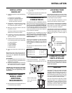
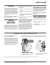
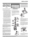
Below Grade Snorkel Installation
If the Snorkel Termination must be
installed below grade, i.e. basement
application, proper drainage must be
provided to prevent water from enter-
ing the Snorkel Termination. Refer to
Dura-Vent Installation instructions for
details.. Do not attempt to enclose the
Snorkel within the wall, or any other type
of enclosure.
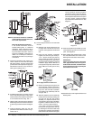
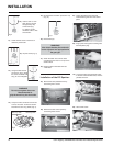
4) Install wall penetration heat shield in the
center of the 9-1/2" round hole and attach
with wood screws. The four wood screws
provided should be replaced with appropri-
ate fasteners for stucco, brick, concrete, or
other types of sidings. Dia. 3.
NOTE: For Snorkel terminations in ABOVE
grade installations, follow national or
local code requirements.
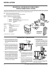
Diagram 2b
Diagram 3
5) If installing termination on a siding covered
wall, a vinyl siding standoff or furring strips
must be used to ensure that the termination
is not recessed into the siding. Dia. 3.
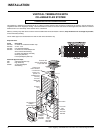
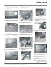
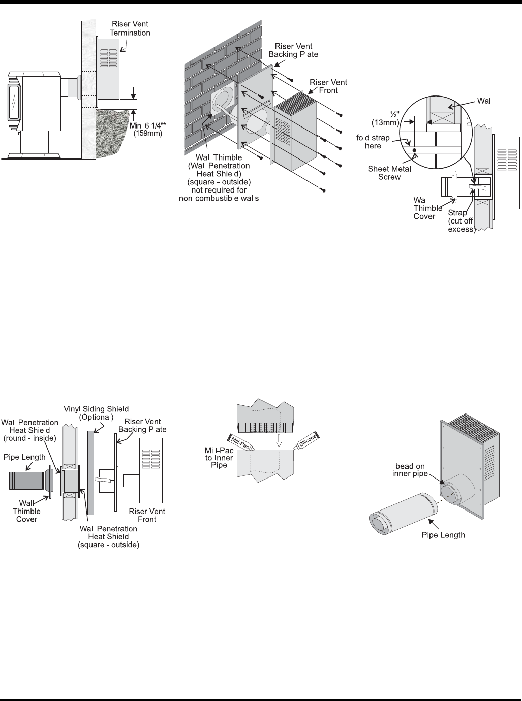
6) Take the Riser Vent terminal and separate
the Backing Plate from the Riser Vent Front
by removing 8 screws as shown in diagram
4.
7) Install the Backing Plate into the wall
penetration heat shield and attach using 4
screws. Dia. 4.
8) Connect all pipe sections to unit and install
into wall:
a) Measure pipe length required and cut
to length. Hint: use the cut end of the
6-5/8" dia. outer pipe at the vent terminal
end.
b) Push the pipe sections completely
together, the minimum pipe overlap is
1-1/4". Secure all outer pipe joints by
using at least two screws. Locate the
screws at the bottom of the pipe so that
the screw heads are hidden on the fi nal
installation. Apply sealant "Mill-Pac" to
inner pipe and high temp silicone seal-
ant or "Mill-Pac" to outer pipe on every
joint.
Hint: Apply sealant to female end.
c) Before connecting the vent pipe to the
vent termination, slide the black deco-
rative wall thimble cover over the vent
pipe, then slide the Wall Penetration
Heat Shield (Part # 946-202) over the
vent pipe. Dia. 3.
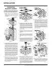
d) Slide the appliance and vent assembly
towards the wall carefully inserting the
vent pipe into the riser vent terminal
assembly. It is important that the vent
pipe extends into the Riser Vent Back-
ing Plate a suffi cient distance so as to
result in a minimum pipe overlap of
1-1/4 inches. Secure the connection
between the vent pipe and the vent cap
by attaching the two sheet metal strips
extending from the Riser Vent Backing
Plate into the outer wall of the vent pipe.
Use two aluminum screws provided to
connect the strips to the pipe section.
Bend any remaining portion of the sheet
metal strip back towards the vent cap and
cut off any excess, it will be concealed
by the decorative wall thimble cover. See
diagram 5.
8) Slide the decorative wall thimble up to the
wall surface being careful not to scratch the
paint. See diagram 5.
9) Back outside: Apply sealant to the 4" inner
fl ue and slide the Riser Vent Front into the
Backing Plate and fasten with 8 screws.
IMPORTANT:
When connecting the pipe to the Riser
Vent, apply Mill-Pac to the inner pipe on
the Riser Vent Terminal, around the bead.
Ensure that the vent pipe is pushed past
the bead for a secure fi t.
10) Seal around the outer edge of the Riser Vent
Backing Plate.
INSTALLATION