


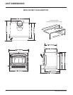
I1200 Regency Wood Insert 9
INSTALLATION
INSTALLING
YOUR INSERT
SAFETY NOTE: The insert is very heavy and
will require two or three people to move it into
position. The insert can be made a little lighter
by removing the cast iron door by opening it and
lifting it off its hinges. Be sure to protect your
hearth extension with a heavy blanket or carpet
scrap during the installation.
NOTE: You will be required to purchase either
the standard or offset 6" diameter (152mm)
fl ue adaptor that is best suited for the specifi c
installation.
List of Tools needed;
- Pull Rod (included with insert)
- 1/2” socket / ratchet
- 3/8 open face wrench
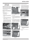
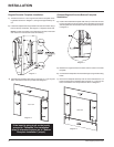
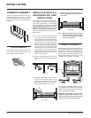
1) Install fl ex liner into existing chimney as
per liner manufacturer’s specifi cations. See
diagram 1.
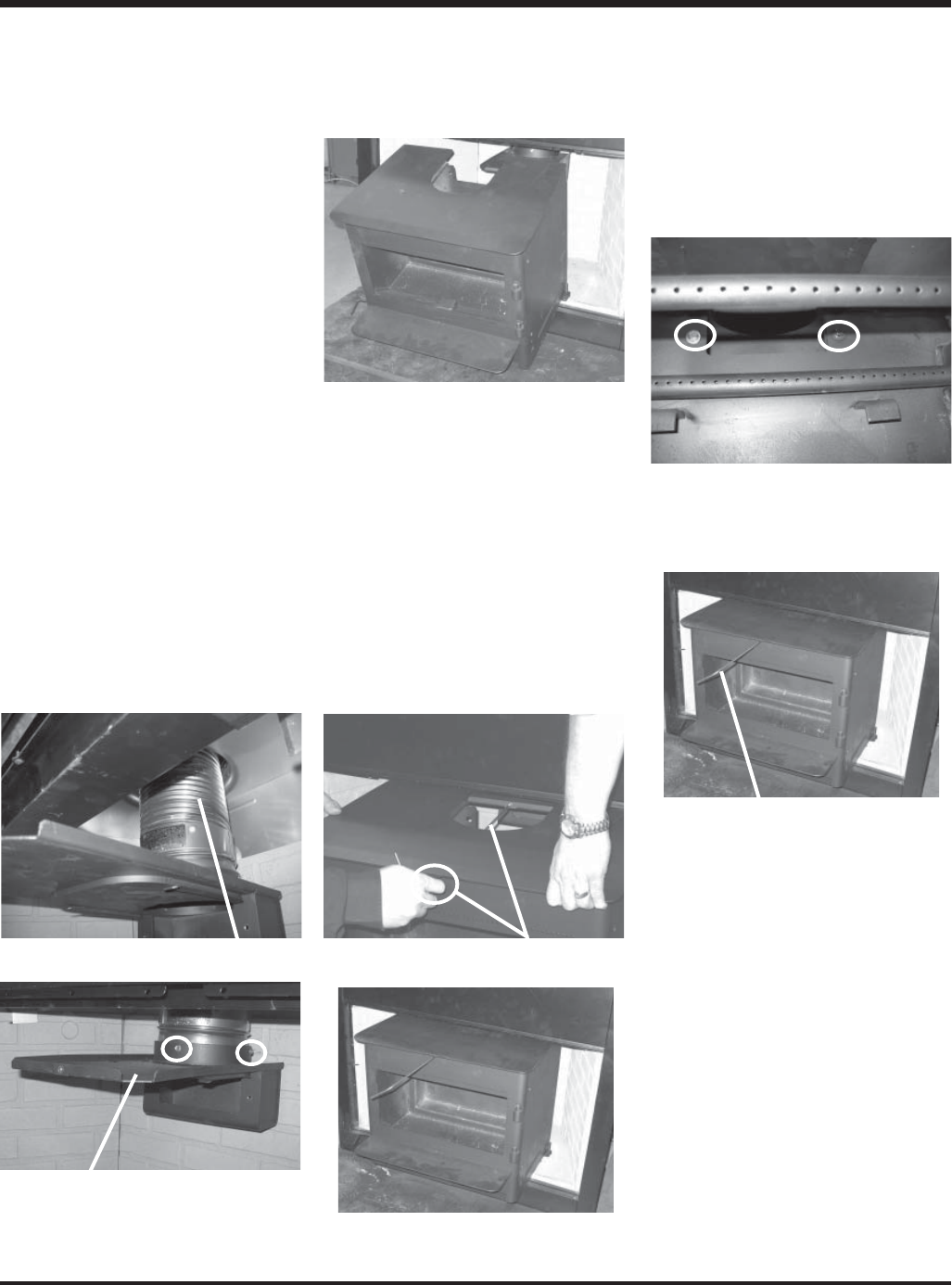
2) Install the required fl ue adaptor onto the end
of the fl ex liner. Secure the adaptor using
3 screws - 1 on the front, left and right side
as shown in diagram 2.
Alignment of the fl ue adaptor can be critical
during the install, it is recommended that the
fl ex liner be left as compressed as possible.
Before inserting the unit the adaptor should
hang, when level, slightly above the required
height.
Secure adaptor using 3 screws - 1 in the
front and 1 each on the left and right side.
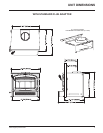
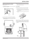
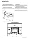
3) Install the unit by fi rst setting the rear of
the unit into the fi replace. See diagram
3. Ensure that the unit is centered in the
existing fi replace and lined up with the fl ue
adaptor.
4) Slide the unit back until the fl ue adaptor is
slightly engaged.
5) At this point it is recommended to level the
unit and ensure that the leveling bolts rest
on the surface of the fi replace. This will keep
the adaptor from binding as the unit is slid
into position.
6) Insert the provided pull rod through the
hole in the top center of the unit. Secure
the threaded end into the fl ue adaptor as
shown in diagram 4. While sliding the unit
into place pull on the rod to ensure that
the fl ue adaptor is properly engaged. See
diagram 5.
Pull Rod
7) Ensure that the unit is still level.
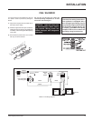
8) To complete the installation and to ensure a
secure fi t and connection of the fl ue adaptor
to the insert, it is essential that the two bolts,
fl at washers and lock washers (supplied
with packaged manual) be installed and
tightened using a 1/2" socket as shown in
diagram 6. This prevents the possibility of
creosote drip and exhaust gas leakage.
9) Remove the pull rod from the top center of
the fi replace. See diagram 7.
10) Re-install the door if removed prior to
installation.
NOTE: The pull rod should not be thrown
away. It should be kept if the stove
is ever needed to be removed from
the fi replace.
Flex Liner
Flue Adaptor
Pull Rod In Place
Pull Rod
Diagram 1
Diagram 2
Diagram 3
Diagram 4
Diagram 5
Diagram 6
Diagram 7